Disc centering device

a disc centering and disc technology, applied in the field of disc players, can solve the problems of deviating laterally, excessive insertion extent, and inability to pull back the small disc by the tapered surface of the clamper, and achieve the effect of increasing the exten

Inactive Publication Date: 2006-10-26
TANASHIN DENKI CO
View PDF0 Cites 6 Cited by
  • Summary
  • Abstract
  • Description
  • Claims
  • Application Information

AI Technical Summary

Benefits of technology

[0012] In an disc player having a chassis, a disc insertion slot formed on the chassis for selectively inserting one of a large and a small size disc, a turntable disposed for rotating on the chassis, a disc insertion path along which the disc is to be passed toward the turntable, a clamper for holding the disc on the turntable, and a clamper support for supporting the clamper, a disc centering device according to the present invention comprises: paired left and right disc sensor members disposed on the chassis and each having one end and the other end; sensor portions each provided on said one end of each of the disc sensor members and leading portions provided on said other end of each of the disc sensor members; a movable member for being moved in the disc inserting direction to an extent corresponding to the diameter of the disc in an interlocked relation to the one of the disc sensor members; a trigger member supported for rocking on the movable member; a disc stopper for the large size disc provided on the trigger member; and a chassis portion formed on the chassis and capable of becoming in contact with the trigger member; whereby as the result of rocking of the trigger member pushed by the outer edge of the disc, said clamper is engaged into the center hole of the disc thereby to effect a disc centering operation; when inserting the small size disc from the disc insertion slot, the disc sensor members undergo synchronous rocking to each other as the sensor portions are pushed by the disc; as soon as the center of the small size disc passes between the two sensor portions, the lateral deviation of the small size disc is corrected by the leading portions of the disc sensor members; when inserting the large size disc from the disc insertion slot, the disc sensor members undergo synchronous rocking to each other to an increased extent compared to the case of inserting the small size disc as the sensor portions are pushed by the disc; with the rocking of the disc sensor members to the increased extent compared to the case of inserting the small size disc, the two leading portions are caused to escape from the disc insertion path along which the large size disc is to be passed, while the trigger member is brought into contact with the chassis portion for limiting the extent of insertion of the large size disc with the trigger member and the disc stopper for the large size disc; and at the time of the small size disc insertion, with the displacement of the movable member the trigger member is brought into contact with a clamper support supporting the clamper for limiting the extent of insertion of the small size disc with the trigger member and the leading portion of the other sensor member.

Problems solved by technology

However, since the disc insertion slot is formed such that the large size disc can also be inserted through it, it is liable that the small size disc is deviated laterally as it is inserted.
For limiting or regulating the extent of insertion of the small size disc, the leading members are desirably disposed at positions in the neighborhood of the disc insertion center line L. Doing so, however, poses a problem.
However, commercially available discs slightly fluctuate in diameter, and in the case of insertion of a small size disc having a less diameter than the standard, the more the leading members are spaced apart from the disc insertion center line L, the more is the excessive insertion extent until the small size disc strikes the leading members.
In this case, it is liable that the small size disc can no longer be pulled back by the tapered surface of the clamper.
As shown above, it is very difficult to set the positions of the leading members such as to fulfill both the function of limiting or regulating the extent of insertion of the small size disc and the function of correcting the deviation of the small size disc.
By so doing, however, the extent of displacement of the clamper is increased to increase the size of the device.

Method used


Image

  • Disc centering device
  • Disc centering device
  • Disc centering device

Examples


Embodiment Construction

[0028] The best embodiment of carrying out the disc centering device according to the present invention will now be described with reference to the drawings.

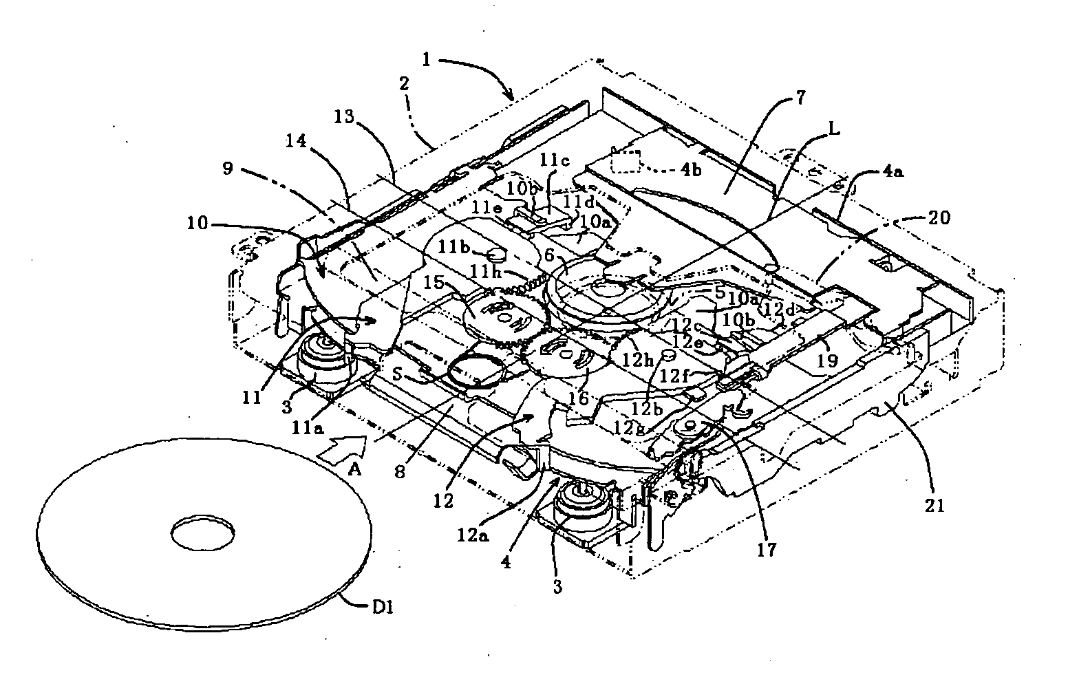
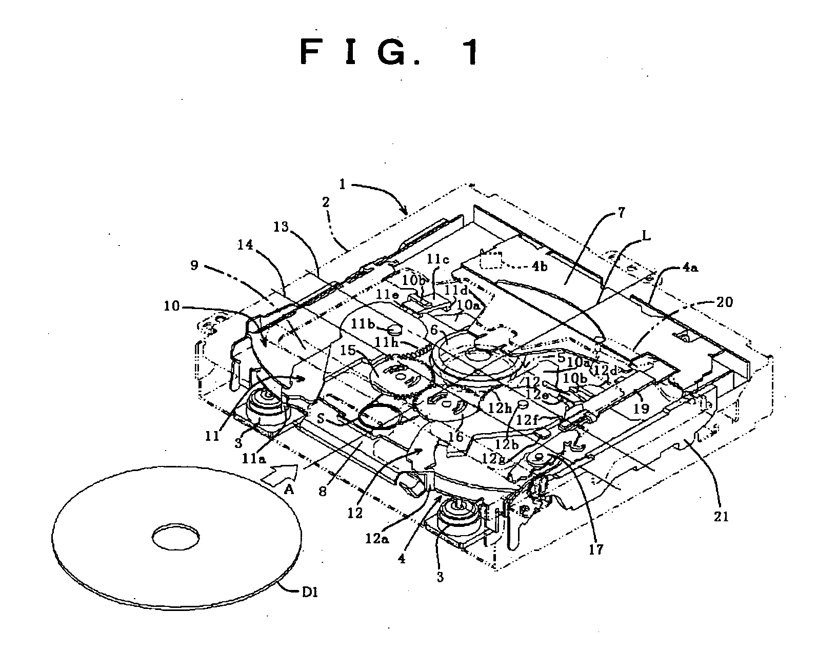
[0029]FIG. 1 is a perspective view showing the internal mechanism of a car-mounted disc player with the disc centering device mounted therein. The outer housing 2 of the device is shown by phantom lines. In the housing 2, a chassis 4 is mounted in a floating state via buffering members 3. Centrally of the chassis 4, a turntable 5 shown by phantom lines is mounted, and also a pick-up (not shown) is mounted such as to be movable between the neighborhood of the turntable 5 and a rear corner of the chassis 4.

[0030] In this specification, by the term “longitudinal direction” of the housing 2 is meant a direction, in which a disc (i.e., small size disc D1 in FIG. 1 or large size disc D2 as shown in FIG. 7 is selectively inserted from a disc insertion slot 8 provided on the front side of the housing 2 in FIG. 1 rearwardly thereof. Al...


PUM

PropertyMeasurementUnit
sizeaaaaaaaaaa
sizeaaaaaaaaaa
sizeaaaaaaaaaa

Abstract

The invention seeks to provide a disc centering device of simple arrangement in a disc player for laying large and small size discs. One of paired, i.e., left and right, leading members and a trigger member also serve as a pair of small size disc stoppers, and the other leading member is provided with the sole function of correcting the deviation of the small size discs. Thus, the problem of the difficulty of positioning by providing the paired leading members with stopper function, is solved with a simple arrangement.

Description

BACKGROUND OF THE INVENTION [0001] 1. Field of the Invention [0002] This invention relates to disc players for selectively playing back one of small and large size discs and, more particularly, to disc centering devices for centering small size discs in the same disc players. [0003] 2. Description of the Prior Art [0004] In a disc player for selectively playing back one of large and small size discs, in which either a small or a large size disc is centered with respect to a turntable by causing engagement of a clamper having a tapered surface in the center hole of the disc, the extent of disc insertion has to be changed according to the diameter or size of the inserted disc. The regulation of the extent of insertion of each disc is made by bringing the disc edge into contact with paired, i.e., left and right, small or large size disc stoppers. The large size disc stoppers are disposed rearwards relative to the small size disc stoppers in the disc inserting direction. Therefore, in t...

Claims


Application Information

Patent Timeline
Patent Type & Authority Applications(United States)
IPC IPC(8): G11B17/04
CPCG11B17/0432
Inventor YOSHIMURA, TOSHIOSHITAMICHI, AKESHI
Owner TANASHIN DENKI CO
Why Eureka
Try Eureka