Filter module with flow control

a filter module and flow control technology, applied in auxillary pretreatment, heating types, separation processes, etc., can solve the problems of unbalanced airflow distribution into the cleanroom, high man-hours cost of balancing a room, and supply hoods coupled to the ductwork to be rebalanced, etc., to facilitate rapid flow setting and/or balancing of airflow.

Active Publication Date: 2006-11-02
CAMFIL USA
View PDF16 Cites 3 Cited by
  • Summary
  • Abstract
  • Description
  • Claims
  • Application Information

AI Technical Summary

Benefits of technology

[0010] A filter module and method for facilitating rapid flow setting and / or balancing of airflow through a plurality of filter modules is provided. In one embodiment, the filter module includes a housing having an opening adapted to receive a filter. An inlet collar is formed through the housing. The filter module contains at least one port configured to provide a metric indicative of flow through the collar. In various other embodiments, at least one port is utilized for sensing differential pressure across a flow restrictor, such as a damper assembly and / or a diffuser plate of the housing assembly, an orifice plate disposed in the collar or ductwork coupled to collar, and the like.

Problems solved by technology

This unbalances the airflow distribution into the cleanroom, often to the point of non-conformance to room balancing criteria.
To remedy this problem, the supply hoods coupled to the ductwork must be rebalanced.
As balancing the airflow requires accurately making airflow measurements and the damper adjustments over a repetitive cycle at each filter, the man-hours cost of balancing a room is high.
Moreover, due to the repetitive nature of airflow measurement gathering and damper adjustment during the balancing procedure, balancing a room undesirably results in lost cleanroom operation time.

Method used


Image

  • Filter module with flow control
  • Filter module with flow control
  • Filter module with flow control

Examples


Embodiment Construction

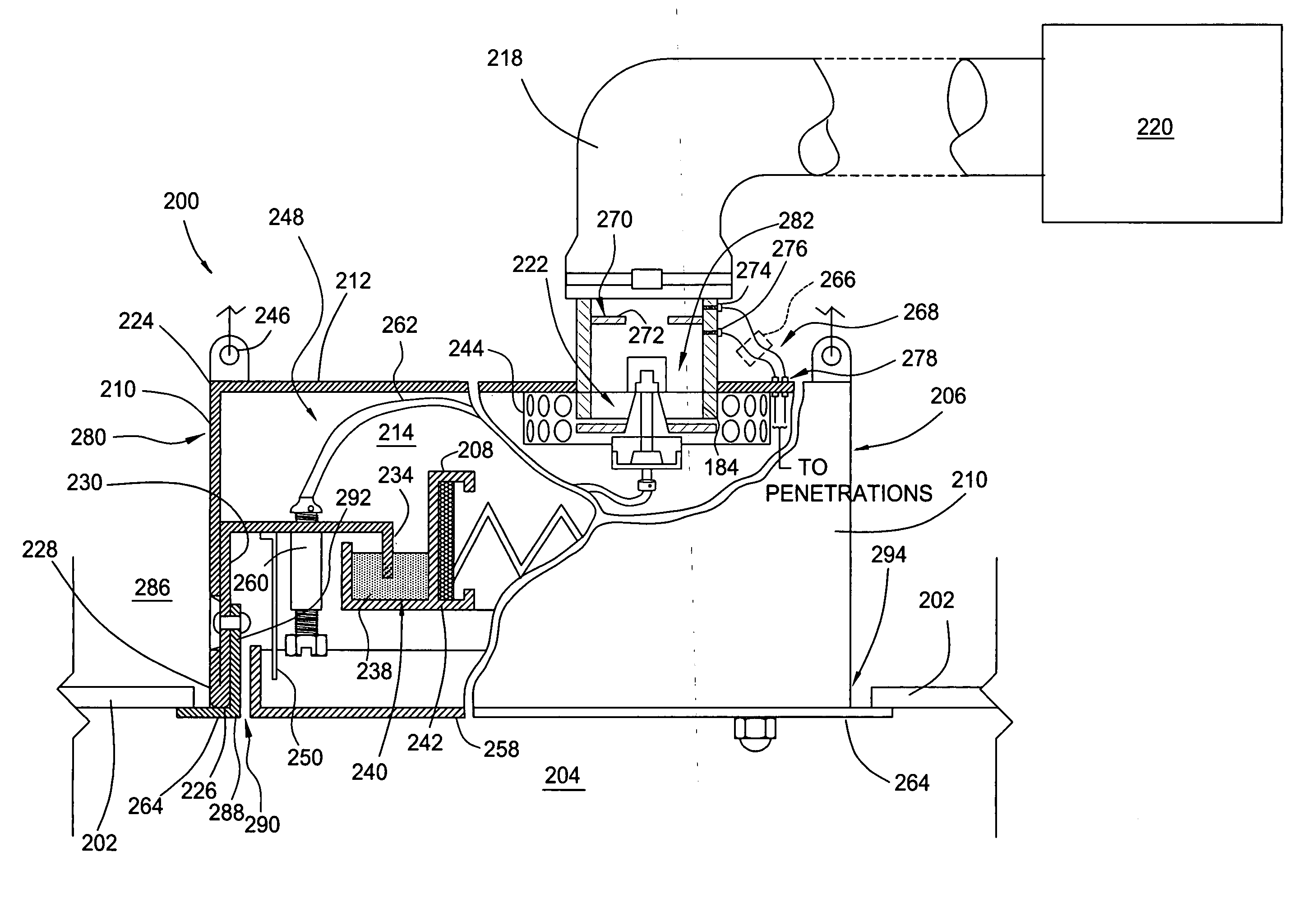
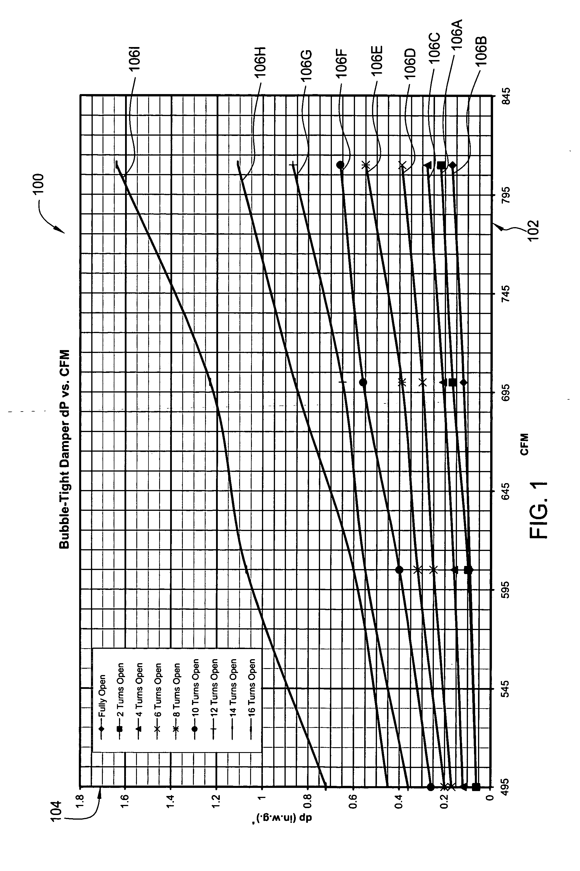
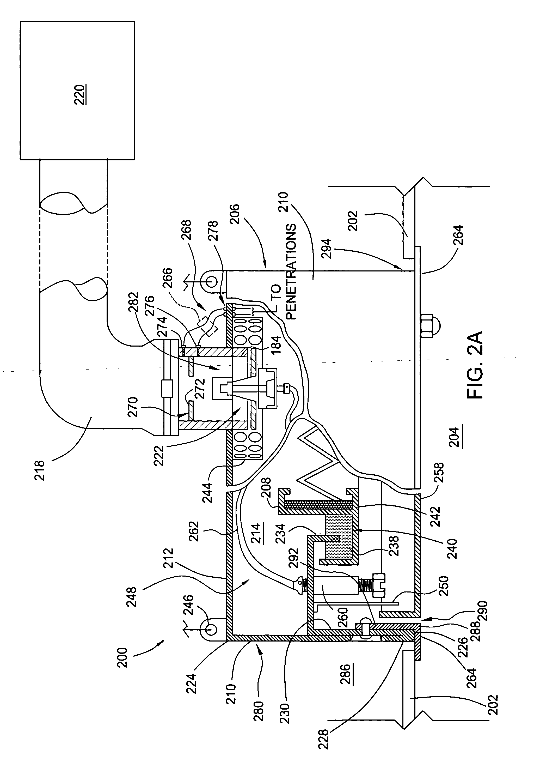
[0030] The invention generally provides a filter module and method for facilitating rapid flow setting and / or balancing of airflow through a plurality of filter modules. In most of the embodiments described herein, pressure drop across a flow restrictor positioned across the flow entering the filter module at a known damper position may be utilized to set the airflow through a filter module without use of flow measuring devices disposed downstream of the filter. For example, at each damper position, pressure drop across flow restrictor, such as the damper itself, or an orifice plate, diffuser plate, and the like, correlates to a specific flow rate through the filter module. The filter module of the present invention provides damper position information visible on the roomside of the filter module when the filter is installed. Thus, by knowing the damper position and the pressure drop, the flow through the filter module may be rapidly set to a predetermined rate. This is extremely ad...


PUM

PropertyMeasurementUnit
pressureaaaaaaaaaa
pressure dropaaaaaaaaaa
flow rateaaaaaaaaaa

Abstract

A filter module and method for facilitating rapid flow setting and/or cost-effective balancing of airflow through a plurality of filters is provided. In one embodiment, the filter module includes at least one port configured to provide a metric indicative of flow through the housing assembly. In various other embodiments, at least one port is utilized for sensing differential pressure across a flow restrictor, such as a damper assembly and/or a diffuser plate of the housing assembly, an orifice plate disposed in a collar or ductwork coupled to collar, and the like. In another aspect of the invention, a method for replacing an air filter is provided that includes the steps of replacing an air filter disposed in a filter housing assembly, and setting a damper position using a damper position indicator to return air flow through the filter to a predetermined rate.

Description

BACKGROUND OF THE DISCLOSURE [0001] 1. Field of the Invention [0002] The embodiments of the present invention relate generally to a filter housing assembly. [0003] 2. Background of the Invention [0004] Clean rooms are utilized in many industries for contamination control and to improve product yields. A plurality of filters, typically mounted in the ceiling of the cleanroom, are configured to remove particulate from air entering the cleanroom at a predetermined efficiency selected based upon the cleanliness requirements of the activities performed in the cleanroom. As particulates load the filtration media disposed in the filter, the airflow through the filter decreases as the pressure drop across the filter increases. Once the filter reaches a critical pressure drop, the filter is typically replaced. [0005] In other applications, replacement of filters is scheduled based on time or processes performed within the cleanroom. For example, in many pharmaceutical and biotech clean rooms...

Claims


Application Information

Patent Timeline
Patent Type & Authority Applications(United States)
IPC IPC(8): B01D46/46
CPCB01D46/4272B01D46/446F24F2011/0093F24F13/28F24F2011/0042B01D2279/51F24F2110/40F24F11/39F24F2140/10
Inventor MORSE, THOMAS C.
Owner CAMFIL USA
Why Eureka
Try Eureka