Permanent magnet generator

a permanent magnet generator and generator technology, applied in the direction of magnetic circuit rotating parts, magnetic circuit shape/form/construction, mechanical energy handling, etc., can solve the problems of reducing the efficiency of the motor and the operating efficiency of the motor system of this type, and achieve the effect of easy starting

Active Publication Date: 2006-11-02
KUNDEL STEPHEN
View PDF31 Cites 44 Cited by
  • Summary
  • Abstract
  • Description
  • Claims
  • Application Information

AI Technical Summary

Benefits of technology

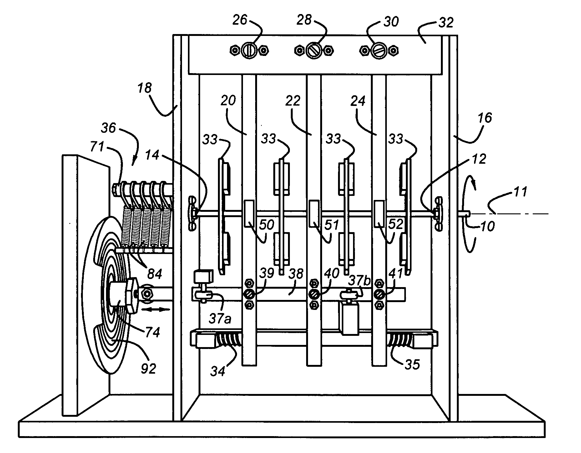
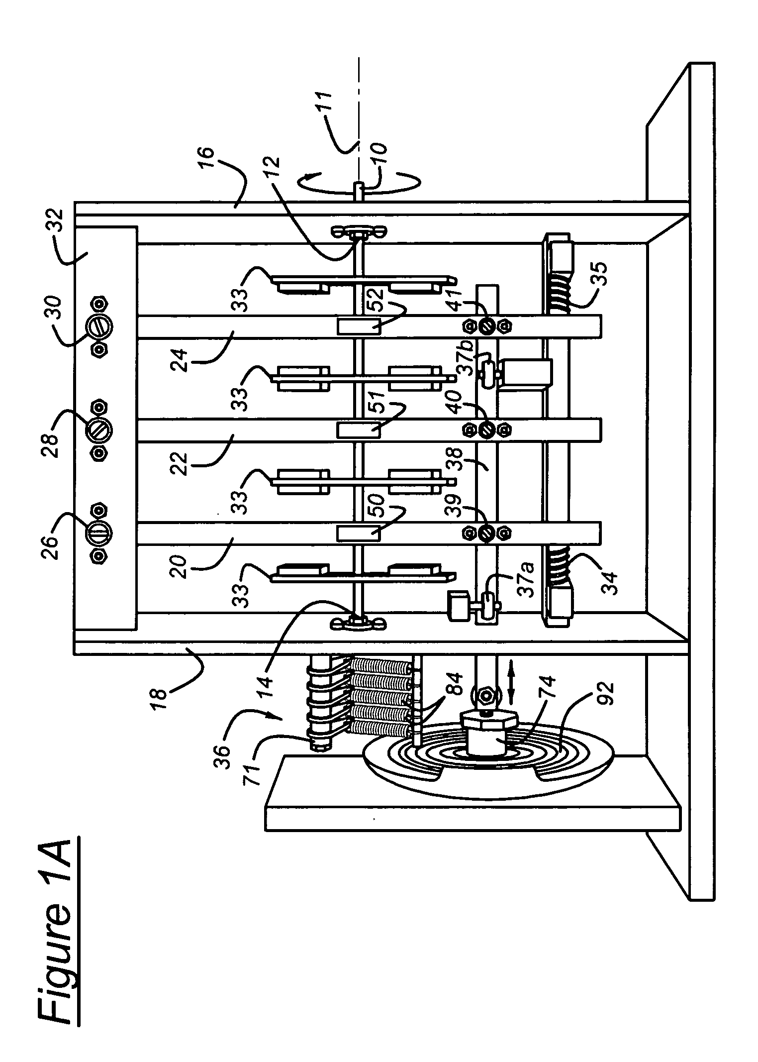
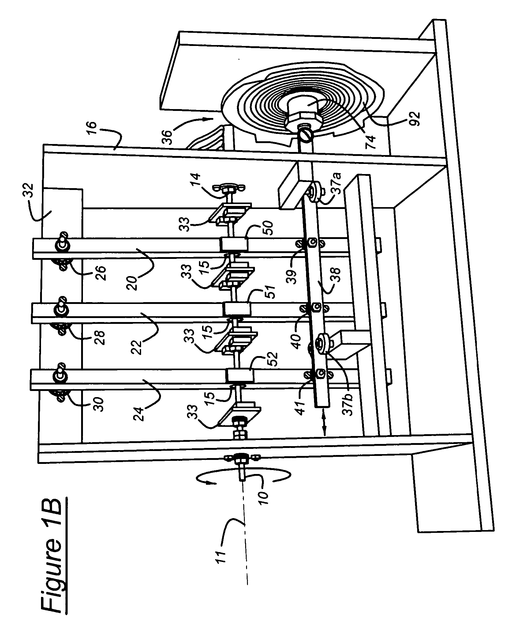
[0008] The drive motor can be easily started by manually rotating the rotor about its axis. Rotation continues by using the actuator to move the reciprocating magnet toward the first rotor magnet pair and away from the second rotor magnet pair when rotor rotation brings the reference pole of the first rotor magnet closer to the opposite pole of the reciprocating magnet, and the opposite pole of the second rotor magnet closer to the reference pole of the reciprocating magnet. Then the actuator moves the reciprocating magnet toward the second rotor magnet pair and away from the first rotor magnet pair when rotor rotation brings the reference pole of the third rotor magnet closer to the opposite pole of the reciprocating magnet, and the

Problems solved by technology

The several energy conversion processes, flow losses and pumping losses decrease the operating efficiency of motor systems of this

Method used


Image

  • Permanent magnet generator
  • Permanent magnet generator
  • Permanent magnet generator

Examples


third embodiment

[0058]FIG. 11 shows the drive motor in which the radial outer portion of the rotor plates 33′ are skewed relative to the axis 11 such that the poles of the rotor magnets 42-49 are canted relative to the poles of the reciprocating magnets 50-52. Operation of the drive motor arranged as shown in FIG. 11 is identical to the operation described with reference to FIGS. 2 and 3.

fourth embodiment

[0059]FIGS. 13 and 14 show the drive motor, in which each of two reciprocating magnets 50, 51 is located on an axially opposite side of a rotor magnet pair 44, 45. Operation of the drive motor arranged as shown in FIGS. 13 and 14 is identical to the operation described with reference to FIGS. 2 and 3.

[0060] The direction of the rotational output can be in either angular direction depending on the direction of the starting torque.

[0061] The drive motor can produce reciprocating output on actuator arm 38 instead of the rotational output described above upon disconnecting actuator arm 38 from actuator 36, and connecting a crank, or a functionally similar device, in the drive path between the actuator and the rotor shaft 10. The crank converts rotation of the rotor shaft 10 to reciprocation of the actuator 36. In this case, the rotor shaft 10 is driven rotatably in either direction by the power source, and the output is taken on the reciprocating arm 38, which remains driveably connect...


PUM


Abstract

A generator for producing electric power includes a drive mechanism, such as a drive motor, having a rotor supported for rotation about an axis. A first generator magnet driveable by the rotor includes a reference pole facing in a first direction. A second generator magnet driveable by the rotor includes a pole of opposite polarity from the reference pole located near the reference pole and facing in the first direction. The first and second generator magnets produce a magnetic field whose flux extends between the reference pole of the first generator magnet and opposite pole of the second generator magnet. A stator includes an electrical conductor winding located adjacent the first and second magnets such that the magnetic field repetitively intersects the winding as the rotor driveably rotates. The drive motor for operating the generator includes a pair of first and second rotor magnets spaced angularly about the axis and supported on the rotor, a reciprocating magnet, and an actuator for moving the first reciprocating magnet cyclically toward and away from the first pair of the rotor magnets, for cyclically rotating the first pair of rotor magnets relative to the reciprocating magnet.

Description

CROSS-REFERENCE TO RELATED APPLICATION [0001] This application is a continuation-in-part of the co-pending U.S. patent application Ser. No. 11 / 116,006, filed Apr. 27, 2005.BACKGROUND OF THE INVENTION [0002] This invention relates to the field of electric power generators. More particularly, it pertains to a generator whose rotor is rotationally driven by a drive motor having mutual attraction and repulsion of permanent magnets. Rotation can be sustained through operation of a low power oscillator. The generator creates electric current by passing multiple magnetic fields produced by an arrangement of permanent generator magnets across windings mounted on a stator as the rotor rotates. [0003] Various kinds of motors are used to drive a load. For example, hydraulic and pneumatic motors use the flow of pressurized liquid and gas, respectively, to drive a rotor connected to a load. Such drive motors must be continually supplied with pressurized fluid from a pump driven by energy convert...

Claims


Application Information

Patent Timeline
IPC IPC(8): H02K35/00H02K47/00
CPCH02K49/10
Inventor KUNDEL, STEPHEN
Owner KUNDEL STEPHEN
Why Eureka
Try Eureka