Eureka AIR delivers breakthrough ideas for toughest innovation challenges, trusted by R&D personnel around the world.

Arrangement for two-dimensional or three-dimensional representation

a two-dimensional or three-dimensional display technology, applied in the field of images, can solve the problems of complex tracking system, reduced brightness in both 2d and 3d display, and limited presentation of common text or two-dimensional graphs

Inactive Publication Date: 2006-11-02
VIA ONE VISION HLDG S A R L +1
View PDF20 Cites 4 Cited by
  • Summary
  • Abstract
  • Description
  • Claims
  • Application Information

AI Technical Summary

Benefits of technology

[0016] Preferably, a second illuminator is provided to enhance the light incident on the front side of the image display device; this second illuminator emits light on the front side of the image display device. This ensures that the arrangement according to the invention can be used in the second mode of operation even in case of low ambient light.
[0018] In another advantageous embodiment, either parts of the second illuminator belong to a touch screen, or a touch screen is attached in front of the second illuminator or the image display device (in the viewing direction). Such a touch screen distinctly enhances the user interaction capability of the arrangement. It is feasible also to use an arrangement for non-contacting detection of the finger position instead of a touch screen.
[0019] Further, it is of advantage if, in the second mode of operation, the illuminating device arranged behind the wavelength filter array is switched off or dimmed down. This feature is intended to homogenize the light used for two-dimensional display.
[0020] In addition, the arrangement according to the invention preferably comprises a computing device for controlling the image display device and the illuminator or illuminators provided. This can be a microcomputer, for example. The latter version is particularly favorable if the arrangement according to the invention is part of a so-called “hand-held PC” or the like, such as a PDA or palm-top PC. Such small computers are often provided with transflective image display devices anyhow, so that the arrangement according to the invention can be integrated very easily.
[0029] It is also feasible, for example, that the wavelength filter array, in its first position, is arranged between the image display device and the illuminating device. In this way it is possible also to achieve a very good 3D impression.

Problems solved by technology

These arrangements, however, frequently allow but a limited presentation of common text or two-dimensional graphs, which is the case, e.g., with U.S. Pat. No. 5,457,574 and U.S. Pat. No. 5,606,455.
As a disadvantage, though, the light has to penetrate two LCD panels, i.e. through a great number of polarizing filters, color filters, liquid crystal layers and other component parts such as carrier substrates, so that brightness is reduced in both 2D and 3D display.
In the 3D mode, this display has the following disadvantages: It is a display for a single viewer; to provide some freedom of movement for the viewer, the arrangement would require a complex tracking system, which could not implemented because of the main component of that arrangement.
Besides, manufacturing the device takes much effort and cost.
The disadvantage of this arrangement is that the luminance available for 2D illumination cannot be made sufficiently homogeneous.
Moreover, if a commercial light guide is used for 2D illumination, its macroscopic structure is visible to the viewer or viewers, as a rule, creating a disturbing moiré pattern, whereas an invisible microscopic structure is difficult and expensive to manufacture.

Method used


Image

  • Arrangement for two-dimensional or three-dimensional representation
  • Arrangement for two-dimensional or three-dimensional representation
  • Arrangement for two-dimensional or three-dimensional representation

Examples


third embodiment

[0037] Preferably, this third embodiment of the arrangement according to the invention also comprises at least one UV lamp, switching on of which produces the second state of the photochromic, color-changing filter elements, and switching off of which produces the first state of the photochromic, color-changing filter elements. In the second state, the photochromic, color-changing filter elements have a distinctly increased light transmittance; therefore, the second state, or the second mode of operation of the arrangement according to the invention, is suitable for two-dimensional display.

[0038] The at least one UV lamp may be arranged behind the wavelength filter array (in the viewing direction), or integrated in a planar illuminator arranged behind the image display device. It is also feasible that the at least one UV lamp is arranged in front of or beside the wavelength filter array if this is arranged in front of the image display device (in the viewing direction).

[0039] In th...

first embodiment

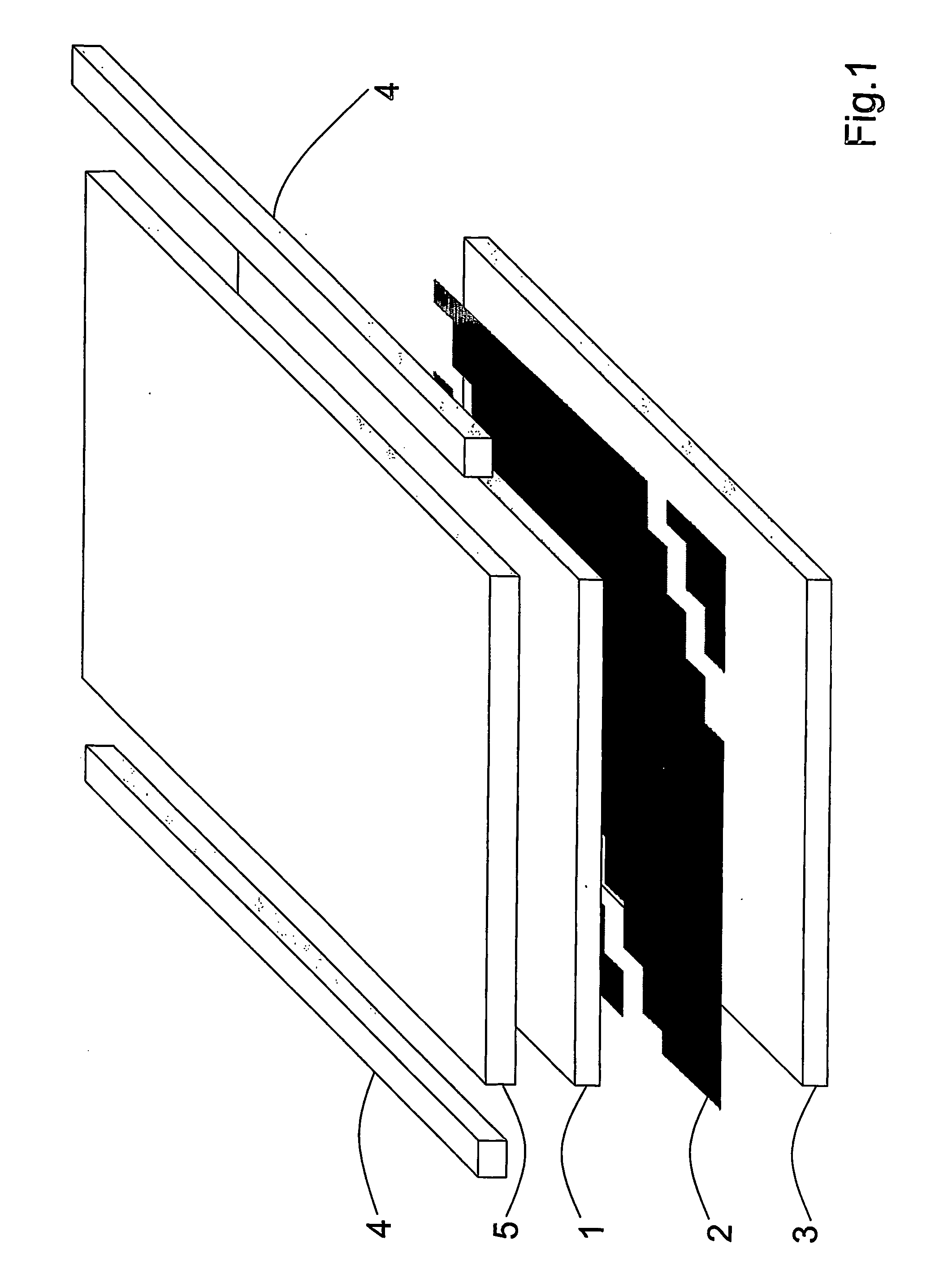
[0054]FIG. 1 is a sketch illustrating the principle of the design of the arrangement according to the invention,

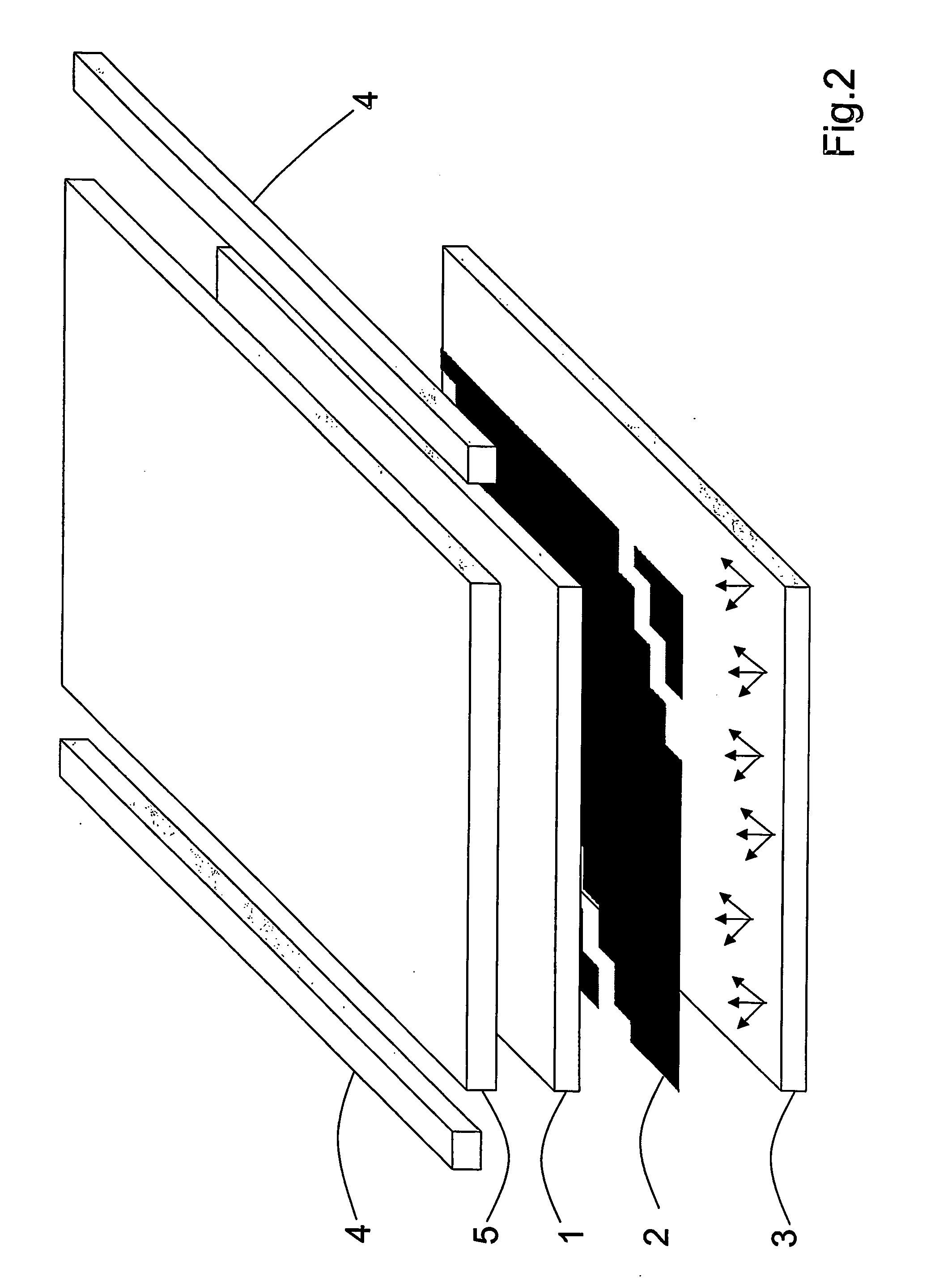
[0055]FIG. 2 is a sketch illustrating the principle of the design of the first embodiment of the arrangement according to the invention, in the first mode of operation,

[0056]FIG. 3 is a sketch illustrating the principle of the design of the first embodiment of the arrangement according to the invention, in the second mode of operation,

second embodiment

[0057]FIG. 4 is a sketch illustrating the principle of the design of the arrangement according to the invention, in the first mode of operation,

[0058]FIG. 5 is a sketch illustrating the principle of the design of the second embodiment of the arrangement according to the invention, in the second mode of operation,

[0059]FIG. 6 is a sketch illustrating the principle of the design of a third embodiment of the arrangement according to the invention in the first mode of operation,

[0060]FIG. 7 is a sketch illustrating the principle of the design of the third embodiment of the arrangement according to the invention, in the second mode of operation,


PUM


Abstract

The invention relates to arrangements for the display of images of a scene or object, that alternatively provides either a three-dimensional or plain two-dimensional visual appearance to several viewers without any aids. In particular, the invention relates to an arrangement comprising a transflective image display device, a plane wavelength filter array arranged behind the image display device (in a viewer's viewing direction), and an illuminator arranged behind the wavelength filter array (in a viewer's viewing direction), in which, in a first mode of operation, light of the illuminator reaches the viewer passing through at least a share of the light-transparent filter elements and subsequently through a share, assigned to them, of the pixels of the image display device, so that the scene or object is visible to the viewer in three dimensions, and, in a second mode of operation, light incident on the front side of the image display device is used, thanks to the transflective properties of the latter, to illuminate it as homogeneously as possible, so that at least part of the scene or object is visible to the viewer in two dimensions.

Description

FIELD OF THE INVENTION [0001] The invention relates to arrangements for the display of images of a scene or object, especially to such that alternatively provide either a three-dimensional or plain two-dimensional visual appearance to one or several viewers without any aids such as, for example, filter goggles. DESCRIPTION OF PRIOR ART [0002] In the course of research in the field of autostereoscopic display, a great number of methods and arrangements have been developed, which give impressions of space to one or several viewers with unaided eyes. These arrangements, however, frequently allow but a limited presentation of common text or two-dimensional graphs, which is the case, e.g., with U.S. Pat. No. 5,457,574 and U.S. Pat. No. 5,606,455. [0003] For users it is of advantage, though, if they can switch between 3D display not requiring special eyeglasses, and high-resolution, least-impaired 2D display on one and the same device. [0004] To achieve this, a number of approaches exist....

Claims


Application Information

Patent Timeline
IPC IPC(8): G09G3/16G02B27/22
CPCH04N13/0411G02B27/2214H04N13/312G02B30/27
Inventor BRUEGGERT, THOMASRELKE, INGO
Owner VIA ONE VISION HLDG S A R L
Why Eureka
Eureka Blog
Learn More