Vertically aligned liquid crystal display having negative compensation film

a liquid crystal display and negative compensation technology, applied in the direction of optical waveguide light guide, bundled fibre light guide, light guide, etc., can solve the problem of light leakage at the viewing angle, and achieve the effect of improving the viewing angle characteristics

Active Publication Date: 2006-11-02
LG CHEM PROSECUTION
View PDF8 Cites 82 Cited by
  • Summary
  • Abstract
  • Description
  • Claims
  • Application Information

AI Technical Summary

Benefits of technology

[0007] Therefore, the present invention has been made in view of the above problems, and it is an object of the present invention to provide an achromatic VA-LCD comprising a negative compensation film, in which contrast at a front sur

Problems solved by technology

However, the conventional VA-LCD using the −C-plate compensation film does not completely compen

Method used


Image

  • Vertically aligned liquid crystal display having negative compensation film
  • Vertically aligned liquid crystal display having negative compensation film
  • Vertically aligned liquid crystal display having negative compensation film

Examples


example 1

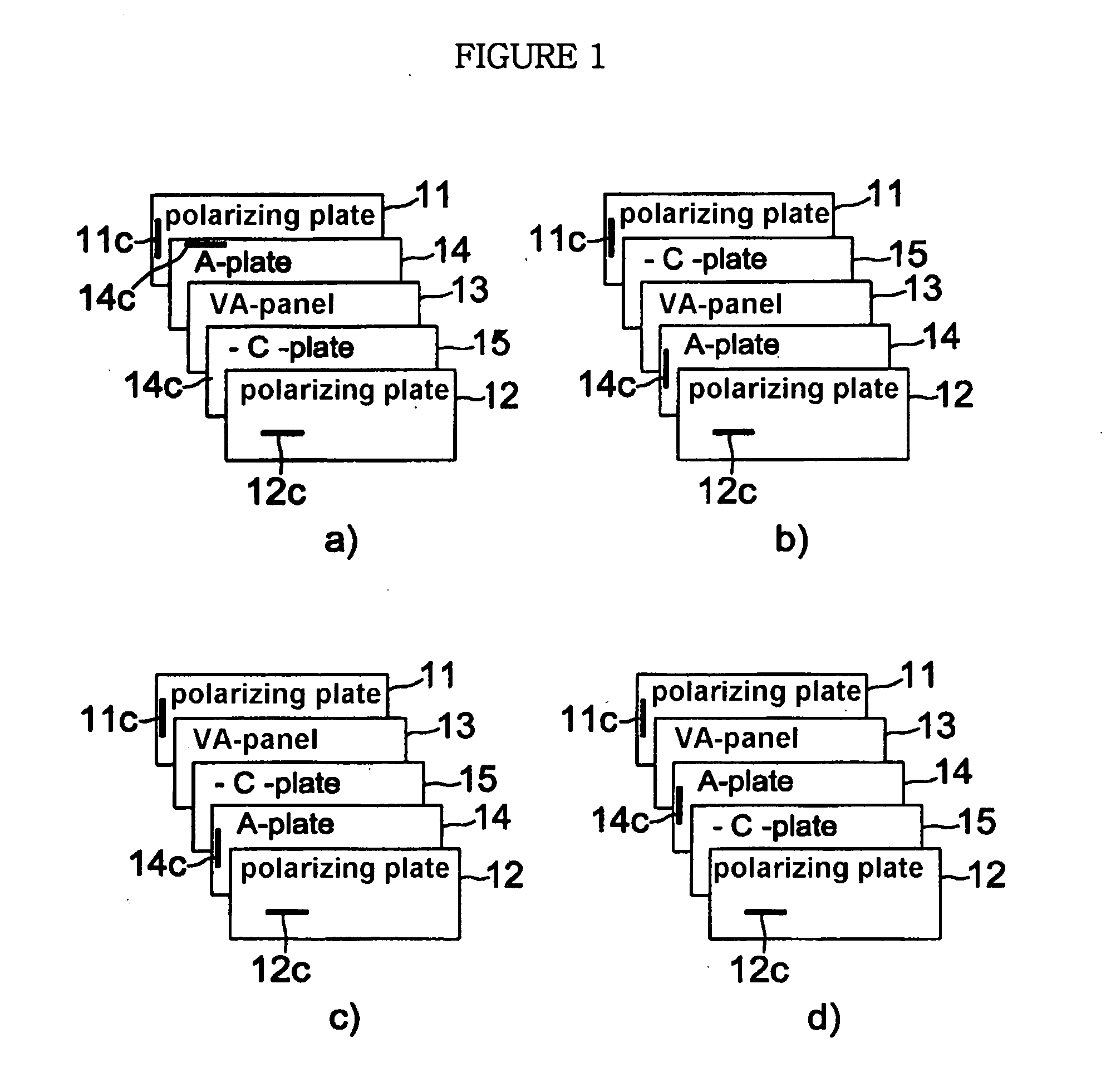
[0029] As shown in FIGS. 1a to 1d, a VA-LCD in accordance with Example 1 of the present invention comprises a vertically aligned panel (VA-panel) 13 obtained by injecting liquid crystal having a negative dielectric anisotropy (Δε0) into a gap between upper and lower glass substrates, two polarizing plates 11 and 12 arranged above the upper and lower surfaces of the VA-panel 13 so that optical absorption axes 11c and 12c are perpendicular to each other, and a negative compensation film including a first retardation film (+A-plate) 14 and a second retardation film (−C-plate) 15, which are arranged between the VA-panel 13 and the polarizing plates 11 and 12.

[0030] In FIG. 1a, a first retardation film (+A-plate) 14 is arranged between the VA-panel 13 and the lower polarizing plate 11, and a second retardation film (−C-plate) 15 is arranged between the VA-panel 13 and the upper polarizing plate 12. Here, the first retardation film (+A-plate) 14 is arranged such that an optical axis 14c ...

example 2

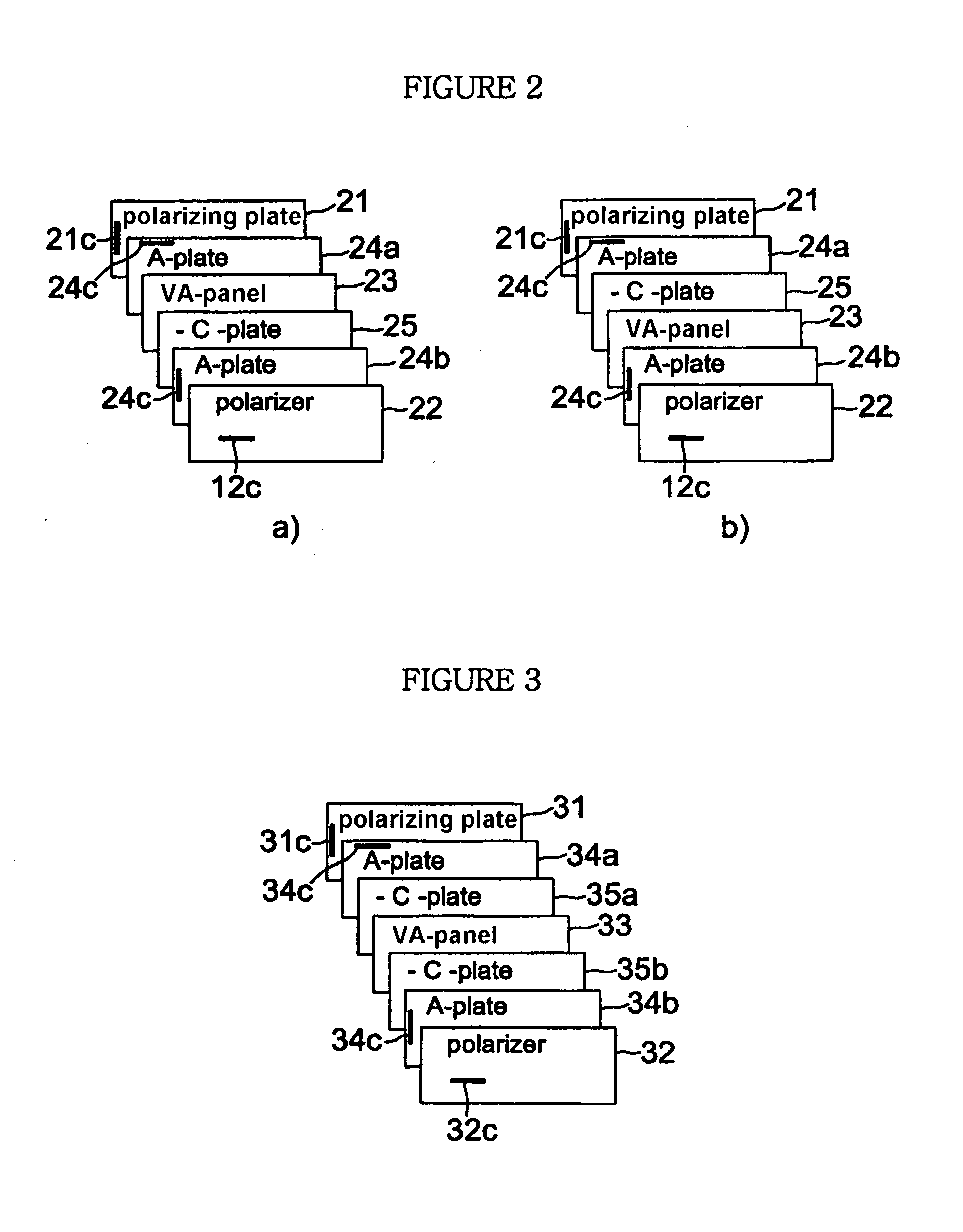
[0034] As shown in FIGS. 2a and 2b, a VA-LCD in accordance with Example 2 of the present invention comprises two polarizing plates 21 and 22 arranged such that optical absorption axes 21c and 22c are perpendicular to each other, a vertically aligned panel (VA-panel) 23 is interposed between the two polarizing plates 21 and 22, and a negative compensation film including two of the first retardation film (+A-plate) 24a and 24b and one of the second retardation film (−C-plate) 25, which are arranged between the VA-panel 23 and the polarizing plates 21 and 22. One of the first retardation films (+A-plates) 24a and 24b and the second retardation film (−C-plate) 25 are arranged at one area between the VA-panel 23 and the upper polarizing plate 22, or between the VA-panel 23 and the lower polarizing plate 21, and the other one of the first retardation film is arranged at the other area between the VA-panel 23 and the upper polarizing plate 22, or between the VA-panel 23 and the lower polar...

example 3

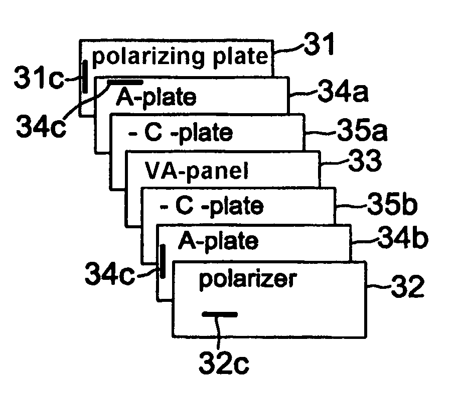
[0037] As shown in FIG. 3, a VA-LCD in accordance with Example 3 of the present invention comprises two polarizing plates 31 and 32 arranged such that optical absorption axes 31c and 32c are perpendicular to each other, a vertically aligned panel (VA-panel) 33 is interposed between the two polarizing plates 31 and 32, and a negative compensation film including two of a first retardation film (+A-plates) 34a and 34b and two of a second retardation film (−C-plates) 35a and 35b, which are arranged between the VA-panel 33 and the polarizing plates 31 and 32. One of the first retardation films (+A-plates) 34a and 34b and one of the second retardation films (−C-plates) 35a and 35b are arranged at one area between the VA-panel 33 and the upper polarizing plate 32 and between the VA-panel 33 and the lower polarizing plate 31, and the other one of the first retardation films (+A-plates) 34a and 34b and the other one of the second retardation films (−C-plates) 35a and 35b are arranged at the ...


PUM


Abstract

The present invention relates to a vertically aligned LCD (VA-LCD) comprising a negative compensation film including one or more of a first retardation film (+A-plate) satisfying the condition of nx>ny=nz and a first retardation film (−A-plate) satisfying the condition of nx<ny=nz, and one or more of a second retardation film (−C-plate) satisfying the condition of nx=ny>nz, wherein the first retardation film is arranged such that its optical axis is perpendicular to an optical absorption axis of a neighboring polarizing plate, and a total thickness retardation (R−C+RVA) including the thickness retardation of the second retardation film and the thickness retardation of a VA-panel has a negative value. The VA-LCD in accordance with the present invention improves contrast characteristics on a front surface and at a tilt angle and minimizes coloring in a black state according to the tilt angle.

Description

TECHNICAL FIELD [0001] The present invention relates to a vertically aligned liquid crystal display (hereinafter, referred to as a “VA-LCD”) using a compensation film having a negative retardation value so as to improve viewing angle characteristics. BACKGROUND ART [0002] As well known to those skilled in the art, a −C-plate compensation film and an A-plate compensation film have been used to compensate for a black state of a VA-LCD under the condition that small drive voltage is applied. U.S. Pat. No. 4,889,412 discloses a conventional VA-LCD using the −C-plate compensation film. [0003] However, the conventional VA-LCD using the −C-plate compensation film does not completely compensate for a black state, thus having a disadvantage such as a leakage of light at a viewing angle. [0004] Further, U.S. Pat. No. 6,141,075 discloses a conventional VA-LCD comprising both the −C-plate compensation film and the A-plate compensation film. [0005] The above VA-LCD comprising both the −C-plate c...

Claims


Application Information

Patent Timeline
IPC IPC(8): G02F1/1335G02F1/13363G02F1/139
CPCG02F1/1393G02F1/133634G02F1/13363
Inventor JEON, BYOUNG-KUNBELYAEV, SERGEYYU, JEONG-SU
Owner LG CHEM PROSECUTION
Why Eureka
Try Eureka