Electrical power source, operational method of the same, inverter and operational method of the same

Inactive Publication Date: 2006-11-02
ORIGIN CO LTD
View PDF3 Cites 25 Cited by
  • Summary
  • Abstract
  • Description
  • Claims
  • Application Information

AI Technical Summary

Benefits of technology

[0017] Further, the measure to prevent cross current as disclosed by the invention on Japanese Patent Application First Publication No. H08-223807, Japanese Patent Application First Publication No. H09-140148, Japanese Patent Application First Publication No. 2001-177997, Japanese Patent Application First Publication No. 2002-262577, Japanese Patent Application First Publication No. 2004-236496, and Japanese Patent Application First Publication No. H08-223

Problems solved by technology

A plurality of storage batteries connected in a series are provided in an uninterruptible power supply system for communication, however, the terminal voltage of these storage batteries are often in a sufficiently low state after an interruption of power or immediately after diagnostics.
When turning on the power switch in this state, over-current, i.e. a large inrush current, flows resulting in a hazardous situation that can break the switch element; therefore, an inrush current prevention circuit is equipped to the electric power source to prevent against inrush current, or a switch element is placed in the inverter to initiate a soft start, in other words, to execute a soft start control that keeps the pulse width small at first and gradually increases the pulse width.
However, when an inrush current prevention circuit is equipped, problems such as the generation of power loss, heat, a drop in reliability, and cost accompany this.
A further problem is the requirement for soft start control circuitry when using a soft start control.
Further, in order to improve the reliability of a power source system employing the inverters, especially, an uninterruptible power supply system, it is common to connect a plurality of inverters in parallel in a construction having a sufficient level of redundancy to load capacity.
However, in case of undertaking parallel operation of inverters, limiting the cross-current to a small value while controlling the pulse width of each of the inverters to regulate the AC output electrical power is difficult.
Voltage differences and current differences occur between inverters when the output voltage approaches the reference value by controlling the pulse width of the switching element of the inverters which makes this t

Method used


Image

  • Electrical power source, operational method of the same, inverter and operational method of the same
  • Electrical power source, operational method of the same, inverter and operational method of the same
  • Electrical power source, operational method of the same, inverter and operational method of the same

Examples


embodiment 1

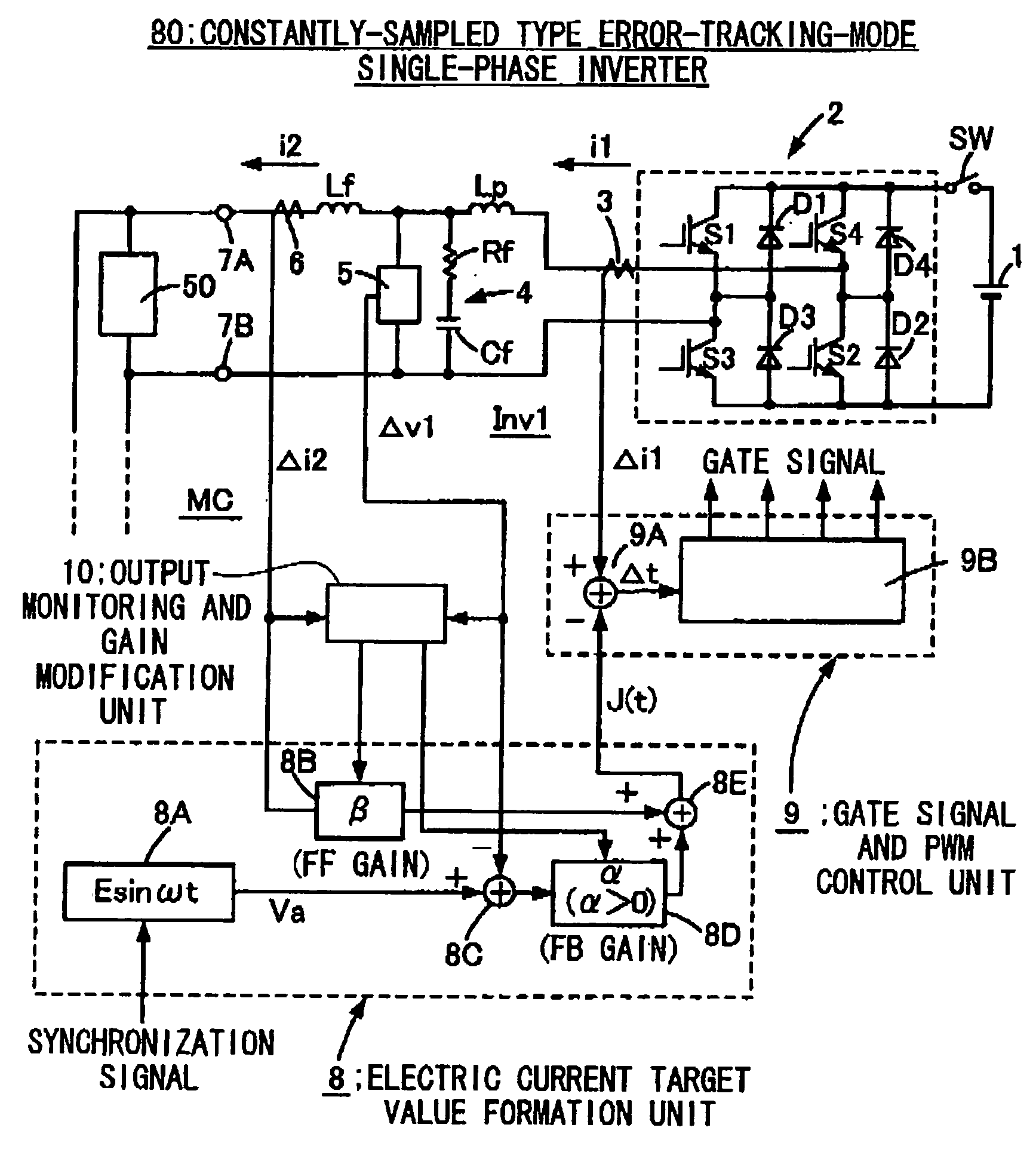
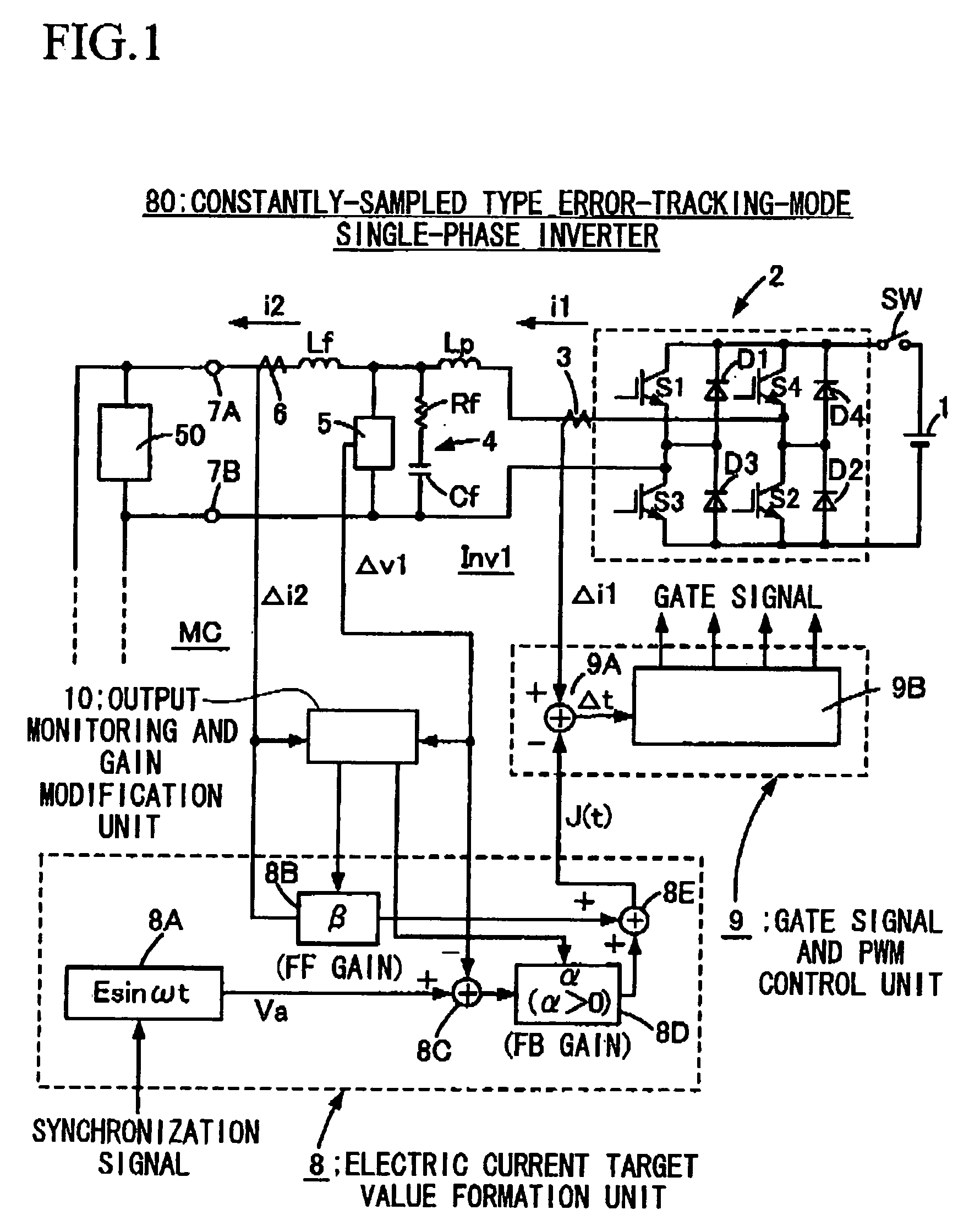
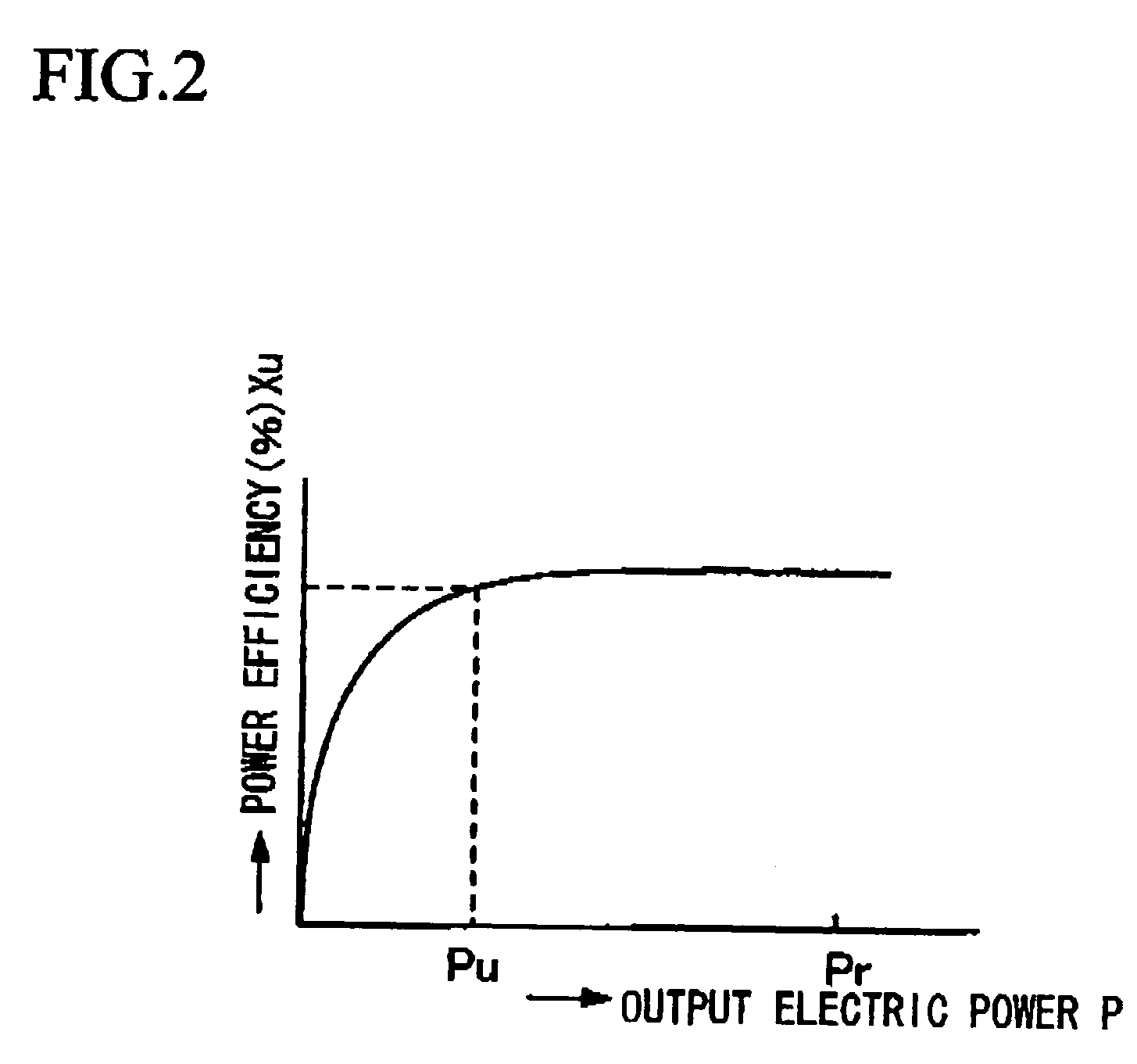
[0076] A description of a preferred embodiment 1 to implement the present invention is explained hereafter with reference to FIG. 1 through FIG. 3. FIG. 1 is a drawing to explain a constantly-sampled error-tracking-mode single-phase AC inverter 80 that is one embodiment of the inverter that has the ability to control equivalent output impedance by only the control parameter adopted by the present invention, and FIG. 2 is a drawing to show one example of the power efficiency of the inverter 80. FIG. 3 is a drawing to explain the single-phase AC power source 100 that is one embodiment of the present invention made by connecting N units of inverters 80 in parallel. First, the constantly-sampled error-tacking single-phase AC inverter 80 consisting of a single-phase inverter is explained with reference to FIG. 1, and the inverter 2 is connected to both ends of the DC power source 1. The DC power source 1 is a common type such as, for example, a rectifier that converts AC to DC by commuta...

embodiment 2

[0105] In the aforementioned embodiment, explanations are given in regards to the error-tracking-mode inverter of a single-phase construction with the error-tracking-mode power source in which those inverters are connected in parallel, as well as the closing and interrupt (suspended) thereof, and because the limiting of the cross-current in the constantly-sampled error-tracking-mode power source in which a plurality of three-phase AC error-tracking-mode inverters are connected in parallel is also performed likewise, an explanation is given in regards to a three-phase AC power source 200 composed of a plurality of tree-phase AC error-tracking-mode inverters 90 connected in parallel with reference to FIG. 4 and FIG. 5. The reference numerals which are the same as those used in FIG. 1 or FIG. 3 indicate the same names in FIG. 4 and FIG. 5. This Embodiment 2 also uses a microcomputer MC, and each analog detection signal is converted to a digital detection signal, and digital processing ...

embodiment 3

[0125] The invention of Embodiment 3 shows, for instance, an inverter having the equivalent output impedance Z that is nearly equal to the resistance value expressed by the formula (1−β·G) / (α·G)[Ω] shown in FIG. 1, and an inverter 100 consisting of the above constantly-sampled error-tracking-mode inverters (single-phase AC power sources) 80(1) and 80(2) which are connected in parallel as shown in FIG. 3, interrupts or closes one of the inverters in an operational state, or an embodiment in which the inverter 100 is opened (paralleled off) from the commercial AC electrical power system. Of course, three or more units of the constantly-sampled error-tacking-mode inverters may be connected in parallel. The following explanation can be applied in the case where three or more units of the constantly-sampled error-tracking-mode inverters are connected in parallel.

[0126] In FIG. 3, the standard sine wave voltage of each inverter 80(1), 80(2) in the inverter 100 are required to be mutually...


PUM


Abstract

The objective of the present invention is to provide a power source and operational method in which a plurality of inverters are connected in parallel with the ability to suppress the crosscurrent with a very simple means. The present invention is an electric power source in which a plurality of inverted operate on the same frequency and the plurality of inverters are connected in parallel so that a resistance value expressed by (1−β·G)/(α·G) here α is the output voltage feedback gain, β is the output current feed forward gain, and G is the inverter current gain, is made to be the equivalent output impedance; and is an electrical power source in which the cross-current between the inverters are made to be an acceptable value or below by adjusting the output of each of the inverters by controlling the equivalent output impedance by modifying both or either one of the output voltage feedback gain α or the output current feed forward gain β.

Description

BACKGROUND OF THE INVENTION [0001] 1. Field of the Invention [0002] The present invention relates to an electric power source, an operational method of the electric power source, an inverter and an operation method of the inverter that has the ability to regulate an output current by adjusting equivalent output impedance by only control parameters. [0003] Priority is claimed on Japanese Patent Application No. 2005-132716, filed Apr. 28, 2005, Japanese Patent Application No. 2005-132717, filed Apr. 28, 2005, and Japanese Patent Application No. 2005-132718, filed Apr. 28, 2005, the content of which are incorporated herein by reference. [0004] 2. Description of Related Art [0005] A plurality of storage batteries connected in a series are provided in an uninterruptible power supply system for communication, however, the terminal voltage of these storage batteries are often in a sufficiently low state after an interruption of power or immediately after diagnostics. When turning on the po...

Claims


Application Information

Patent Timeline
IPC IPC(8): H02M7/537
CPCH02M7/53871H02M7/493
Inventor OHSHIMA, MASAAKIUSHIKI, SHUUICHIFUKUI, JIROU
Owner ORIGIN CO LTD
Why Eureka
Try Eureka