Switching Device and Method

a technology of switching device and switch, applied in the field of switches, can solve problems such as preventing the switch from functioning as desired

Inactive Publication Date: 2006-11-02
HMI SYST
View PDF21 Cites 6 Cited by
  • Summary
  • Abstract
  • Description
  • Claims
  • Application Information

AI Technical Summary

Benefits of technology

[0007] A switch according to the teachings of the present invention may include an optical transmitter for transmitting light along a path and an optical receiver positioned within the path for providing an actuating signal responsive to the light from the optical transmitter, wherein an arm member is movable between a blocking position

Problems solved by technology

It is well known to those skilled in the art that problems result when electrical

Method used


Image

  • Switching Device and Method
  • Switching Device and Method
  • Switching Device and Method

Examples


Embodiment Construction

[0019] The present invention will now be described more fully hereinafter with reference to the accompanying drawings, in which embodiments of the invention are shown by way of illustration and example. This invention may, however, be embodied in many forms and should not be construed as limited to the embodiments set forth herein. Rather, these embodiments are provided so that this disclosure will be thorough and complete, and will fully convey the scope of the invention to those skilled in the art.

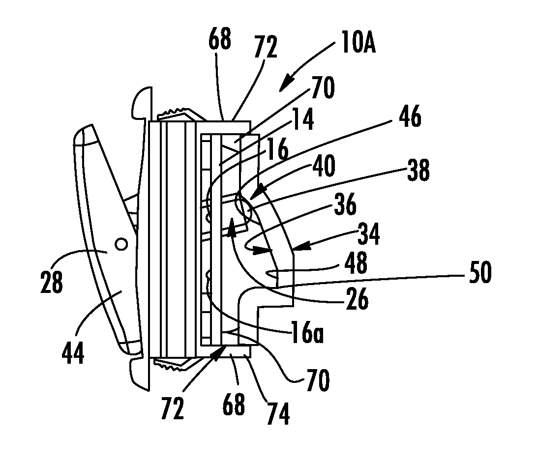
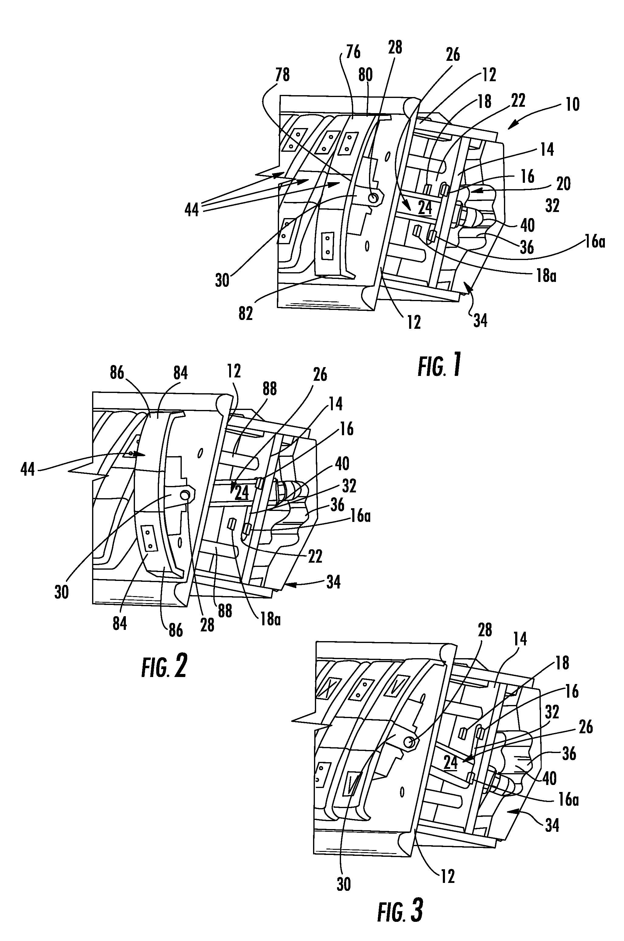
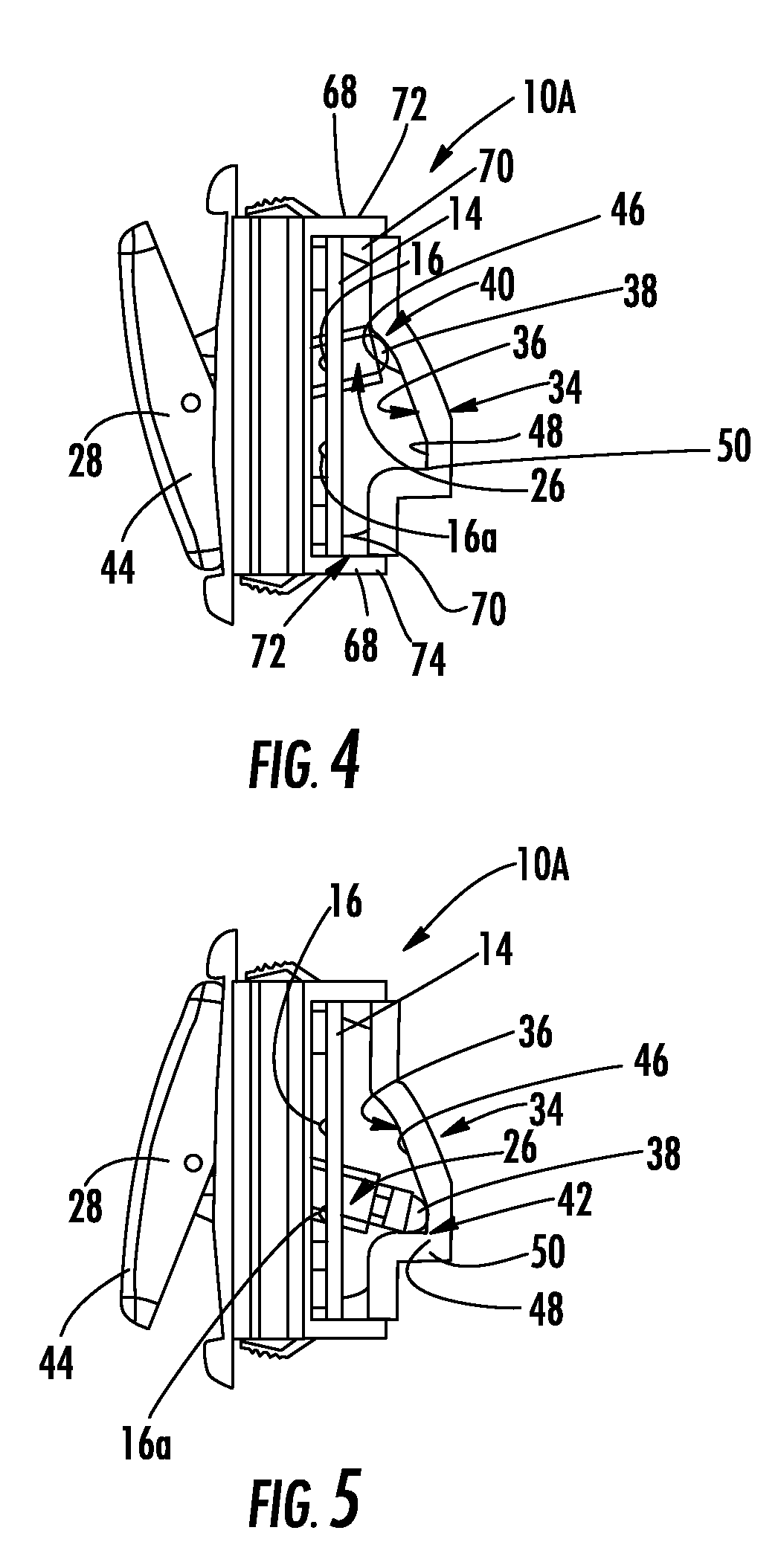
[0020] With reference initially to FIG. 1, one embodiment of eth present invention may include a switch 10 having a base 12. A printed circuit board 14 is carried by the base 12 with an optical transmitter 16 and an optical receiver 18 carried by the printed circuit board. For the embodiment herein described, by way of example, the optical transmitter 16 and optical receiver 18 form part of an actuator 20 operable for emitting light along a beam path 22 wherein the optical receiver 18 i...


PUM


Abstract

A rocker styled switch includes an arm member moveable into and out of a beam path transmitting light between an optical transmitter and an optical receiver for blocking and allowing light to reach the receiver for providing an actuating signal. An end of the arm member includes a cam follower moveable along a contoured cam surface for causing a preferential movement of the arm member from an unstable position to a stable position responsive to the cam surface for defining a switching operation. Interchangeable cam surfaces provide a one position momentary switch, a two position momentary switch, a two position stationary switch, and a three position stationary switch.

Description

CROSS-REFERENCE TO RELATED APPLICATIONS [0001] This application claims the benefit of U.S. Provisional Application No. 60 / 674,569 for “Switching Device and Method” having filing date Apr. 25, 2005, the disclosure of which is incorporated herein by reference in its entirety, and commonly owned.FIELD OF THE INVENTION [0002] The present invention generally relates to switches and in particular to a switch for providing selectable switching including momentary and stationary switching modes. BACKGROUND OF THE INVENTION [0003] Typical rocker and toggle switches known in the art use a plunger to move electrical contacts into different positions to create a signal for activating and de-activating an electrical device connected to the switch. It is well known to those skilled in the art that problems result when electrical contacts corrode over time, thus preventing the switch from functioning as desired. By way of example, while switches actuated by a rocker member are widely used for user...

Claims


Application Information

Patent Timeline
IPC IPC(8): G02B6/26
CPCH01H21/50H01H23/003H01H23/02H01H23/025H01H23/168H03K17/968H01H23/24H01H23/28H01H2219/062H01H2239/022H01H2239/024H01H23/205H01H2011/0043
Inventor BATEMAN, DAVID E.BULLOCK, TODD M.
Owner HMI SYST
Why Eureka
Try Eureka