
Carousel system for automated chemical or biological analyzers employing linear racks

a technology of linear racks and chemical or biological analyzers, applied in chemical methods analysis, transportation and packaging, instruments, etc., can solve the problem of general difficulty in retrieving samples at different times to perform different tests

Active Publication Date: 2006-11-02
SIEMENS HEALTHCARE DIAGNOSTICS INC
View PDF54 Cites 47 Cited by
  • Summary
  • Abstract
  • Description
  • Claims
  • Application Information

AI Technical Summary

Benefits of technology

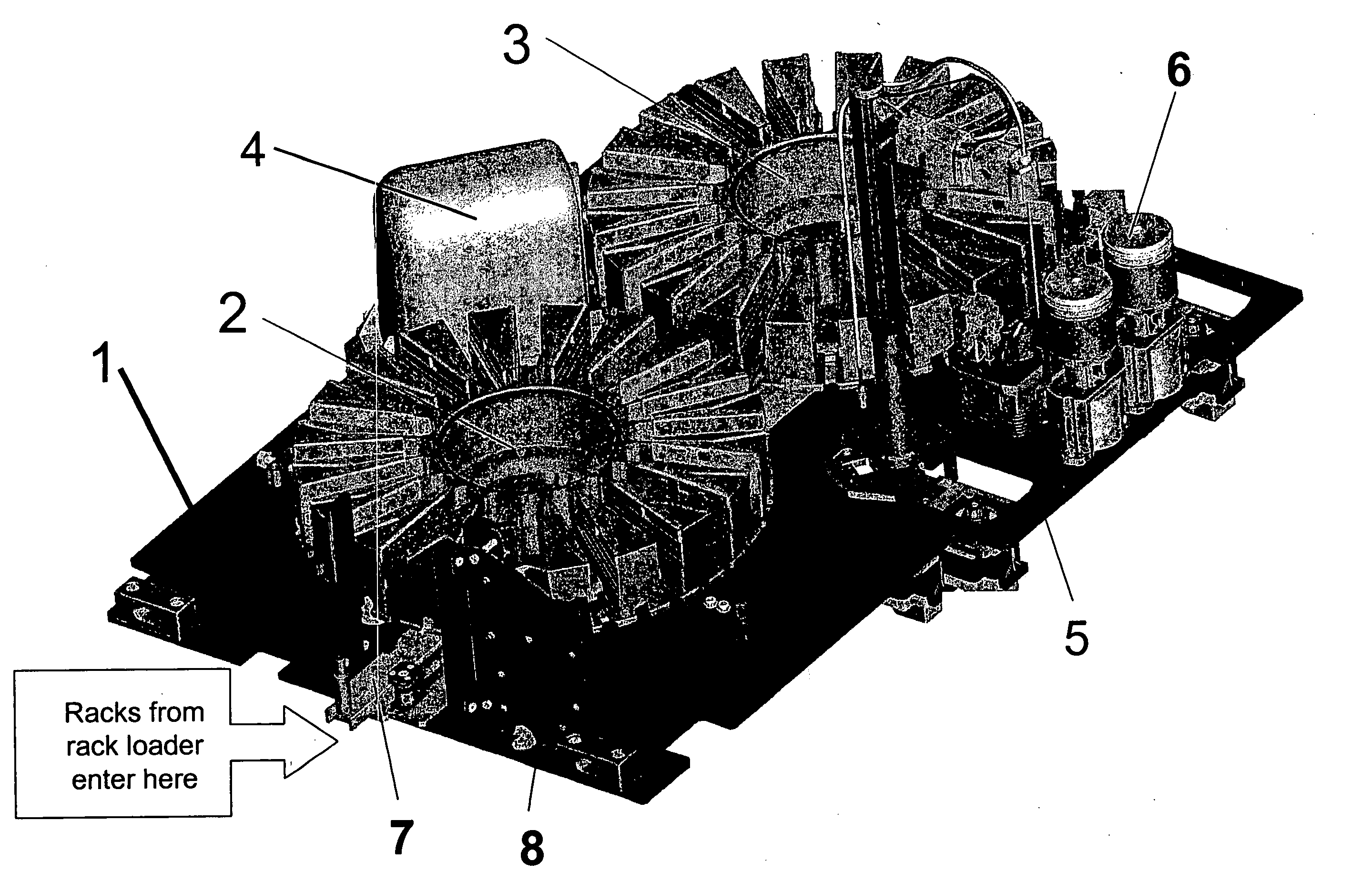
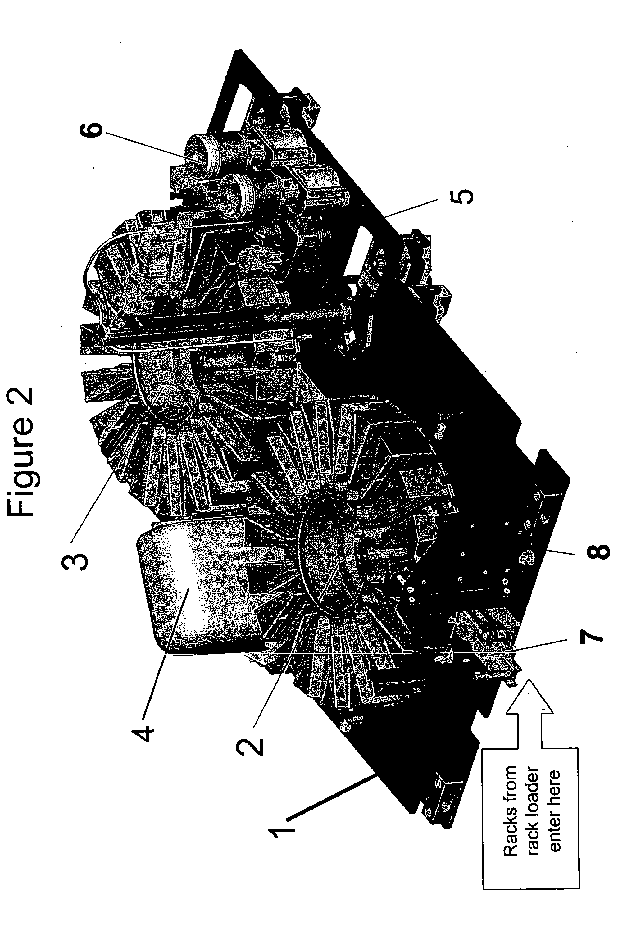
[0005] According to the invention, an improved sample handling system, which may be incorporated into automated chemical or biological (e.g., immunoassay) analyzers, includes one or more carousels with radially distributed slots, each of which can accommodate a linear rack containing a plurality of samples or controls distributed along the length of the linear rack. The linear racks preferably include receptacles for holding containers (e.g., test tubes) filled with samples or controls, and, more preferably, the containers can be of varying sizes. Preferably, the test tubes are labeled with a bar code or an RFID tag identifying the contents of the tube, and the linear racks are also labeled with a bar code or RFID tag. In a preferred configuration using bar coding, the bar codes on the test tubes and on the linear racks can be read at the same time using the same bar code reader. In operation, a computer controller will track information related to the location of linear racks and test tubes, and by associating bar code or RFID identity information of the rack and bar code or RFID identity information of the test tubes, the controller can easily manage retrieval, transfer, and pipetting operations of samples which need to be accessed a number of different times (e.g., for performing different tests on the same sample). Bar code labels may be permanently imprinted on linear racks or labels may be printed and applied to linear racks as well as to test tubes. Similarly, RFID tags might be affixed to and removable from both linear racks and test tubes.
[0008] Movements of the one or more carousels, the mechanical transfer devices, pipetters and other components in the chemical and biological analyzer are preferably accomplished under computer control so as to minimize or eliminate involvement of technicians. This is accomplished by tracking the linear rack that is labeled with a bar code, RFID tag, or other device, tracking the positions of the linear racks in the carousel or carousels as well as the testing to be performed on the samples in the linear racks, and coordinating the movements of the transfer devices and pipetters.
[0010] In one embodiment of the invention, controls are loaded into the carousel system on a linear rack in the same fashion as samples to be tested. These controls can be selectively stored in a slot on the carousel, or, more preferably, be stored in a storage area separate from a carousel. Transfers from the carousel to the storage area will be accomplished with a mechanical transfer device operating under computer control in the same fashion as discussed above. The controls can be selectively retrieved (e.g., transferred back onto the carousel followed by the carousel being rotated to pipetting position), for periodic calibration or testing of the automated chemical or biological analyzer, and then re-loaded into the storage compartment. In this embodiment, the user is not required to load controls by a separate operation (i.e., controls can be automatically loaded into the machine from the rack loader used for transporting linear racks of samples), and the controls can be periodically used multiple times without interrupting the operations of the chemical or biological analyzer.

Problems solved by technology

While the carousel systems have the advantage of easy access to large numbers of samples, the prior art systems suffer from having to empty the carousels in a batch like process in order to handle new samples.
Conversely, while the linear rack based systems allow for easy automation, it is generally more difficult to retrieve a sample at different times to perform different tests.

Method used


Image

  • Carousel system for automated chemical or biological analyzers employing linear racks
  • Carousel system for automated chemical or biological analyzers employing linear racks
  • Carousel system for automated chemical or biological analyzers employing linear racks

Examples


Embodiment Construction

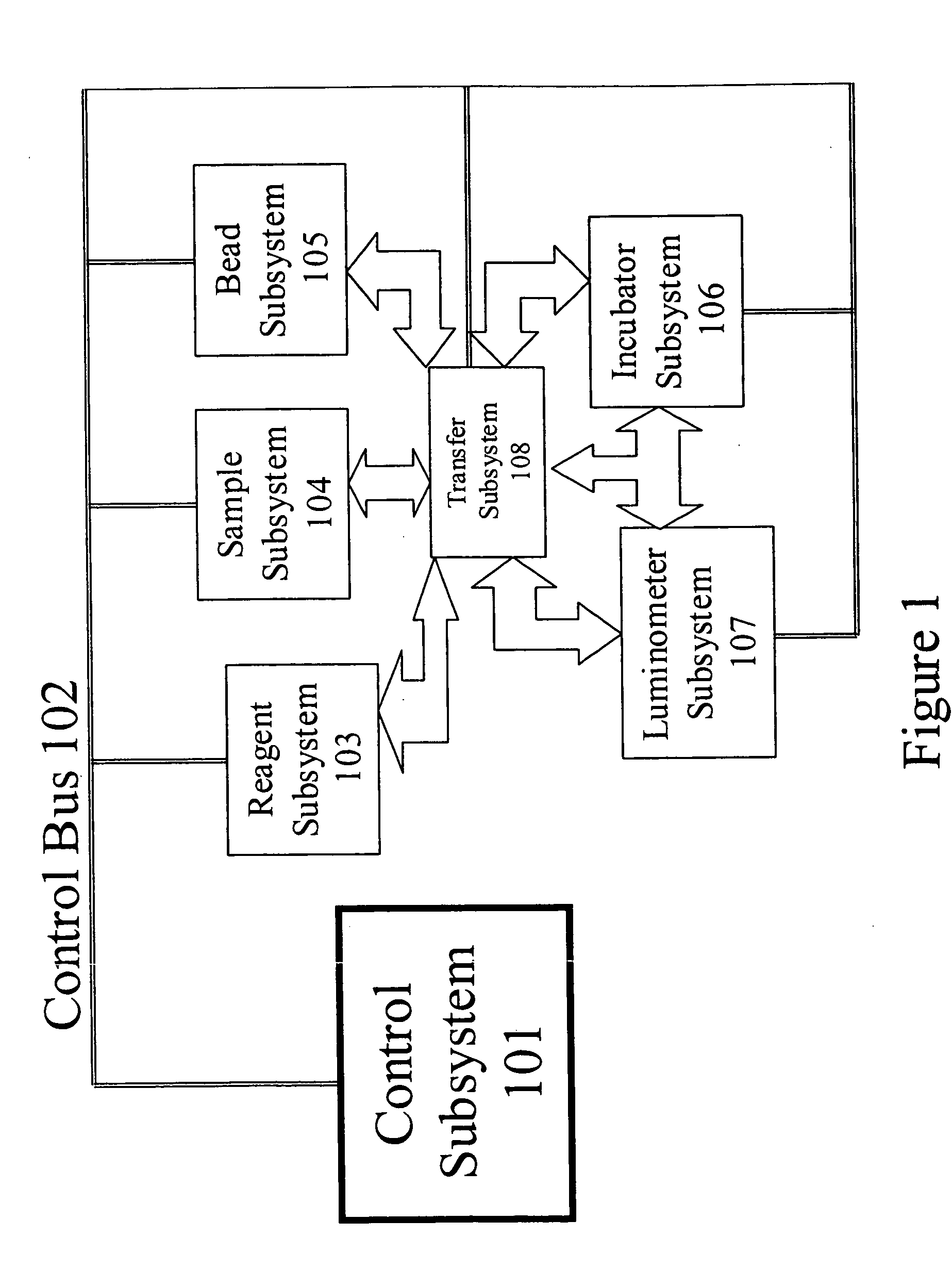
[0019] For illustrative purposes only, FIG. 1 shows the subsystems for performing operations in an automated immunoassay analyzer; however, it should be understood that this invention can be practiced with chemical analyzers per se, and is not limited to use in automated immunoassay analyzers. Automated immunoassay analyzers are complex systems designed to process large numbers of patient samples obtained at a clinic or hospital with minimal involvement of a technician. It should be understood that this invention provides for sample handling in a highly automated and flexible manner, and may be amenable for use in a variety of existing automated chemical or immunoassay analyzers or could be incorporated in the future into newer automated chemical or immunoassay analyzers.

[0020] At its core, the control system 101 manages and coordinates the operations of all of the subsystems by sending commands and be receiving signals from the subsystems via the control bus 102. In operation of a...


PUM


Abstract

An automated chemical or biological sample analyzer includes a plurality of linear sample carrying racks that are moved to a processing station for conducting an analysis using one or more carousel devices. Under computer control, rotational movements of the carousel or carousels, linear movements of the transfer or shuttle mechanisms, and operation of a pipetting station are performed in a coordinated fashion so as to handle the processing of a large number of samples simultaneously in an optimized fashion that allows random ordering of samples for processing.

Description

FIELD OF THE INVENTION [0001] The present invention generally relates to automated chemical analyzers, such as, for example, automated immunoassay analyzers, and more particularly, to a carousel system which handles linear racks, each of which hold a plurality of samples or controls. The invention thus combines the immediate access to samples benefits of a carousel system with the benefit of enhanced automation by sequential presentation offered linear rack based systems. BACKGROUND DESCRIPTION [0002] Automating chemical analyses is a desirable objective in a number of situations. For example, in the clinic or hospital setting, a large number of patient blood or urine samples need to be analyzed on a daily basis for a wide variety of different antigens or analytes. Highly advanced systems have been developed for analyzing these types of samples, and for allowing different tests to be performed on different samples as well as for recording test results for subsequent use in, for exam...

Claims


Application Information

Patent Timeline
IPC IPC(8): B65G1/00
CPCG01N35/00693G01N35/0095G01N35/025G01N2035/00574Y10T436/113332G01N2035/00782G01N2035/0444G01N2035/0465G01N35/026G01N2035/00752
Inventor BABSON, ARTHUR L.
Owner SIEMENS HEALTHCARE DIAGNOSTICS INC
Learn More