

Snowmobile lifting device
- Summary
- Abstract
- Description
- Claims
- Application Information
AI Technical Summary
Benefits of technology
Problems solved by technology
Method used
Image

Examples
Embodiment Construction
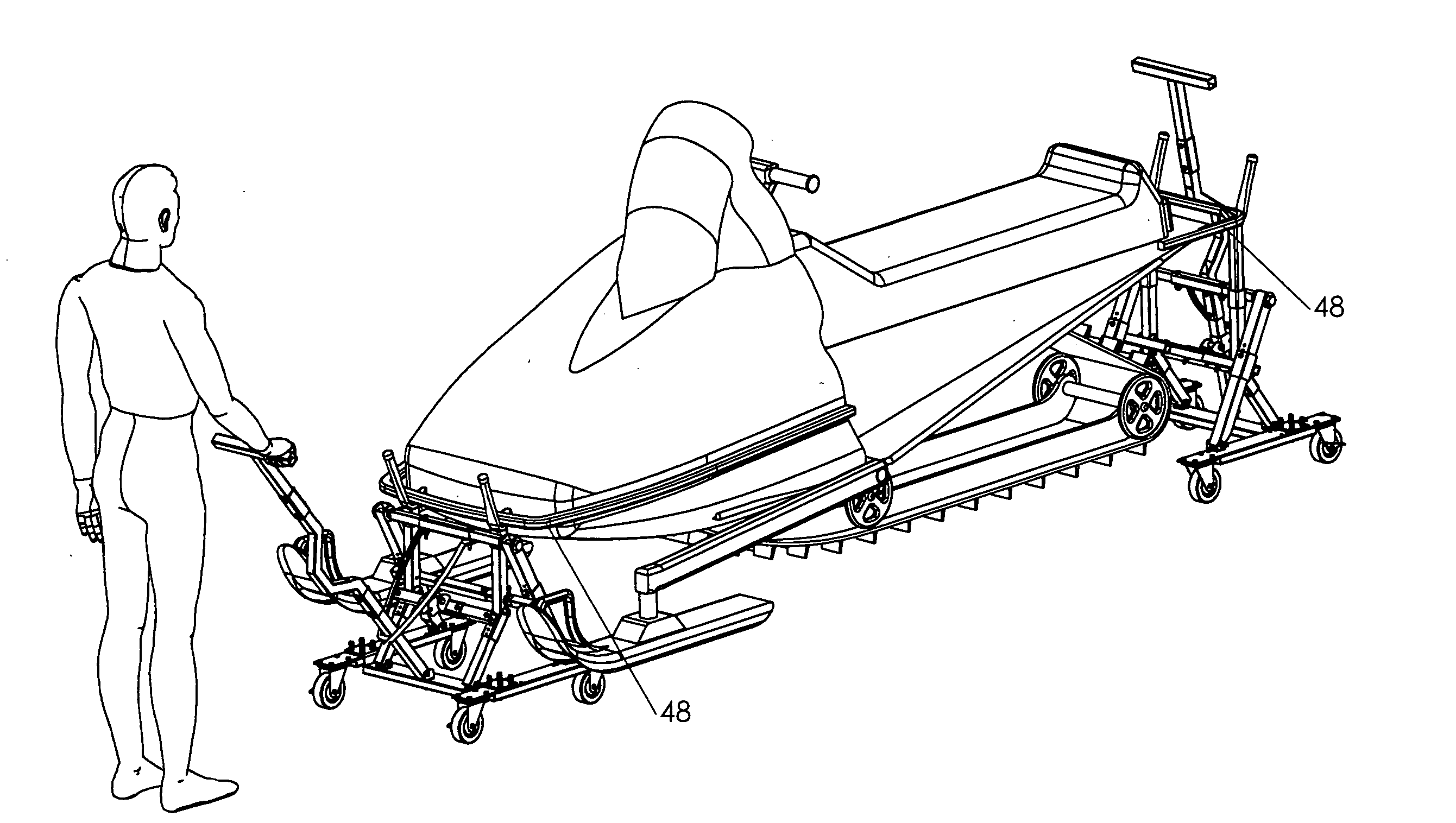
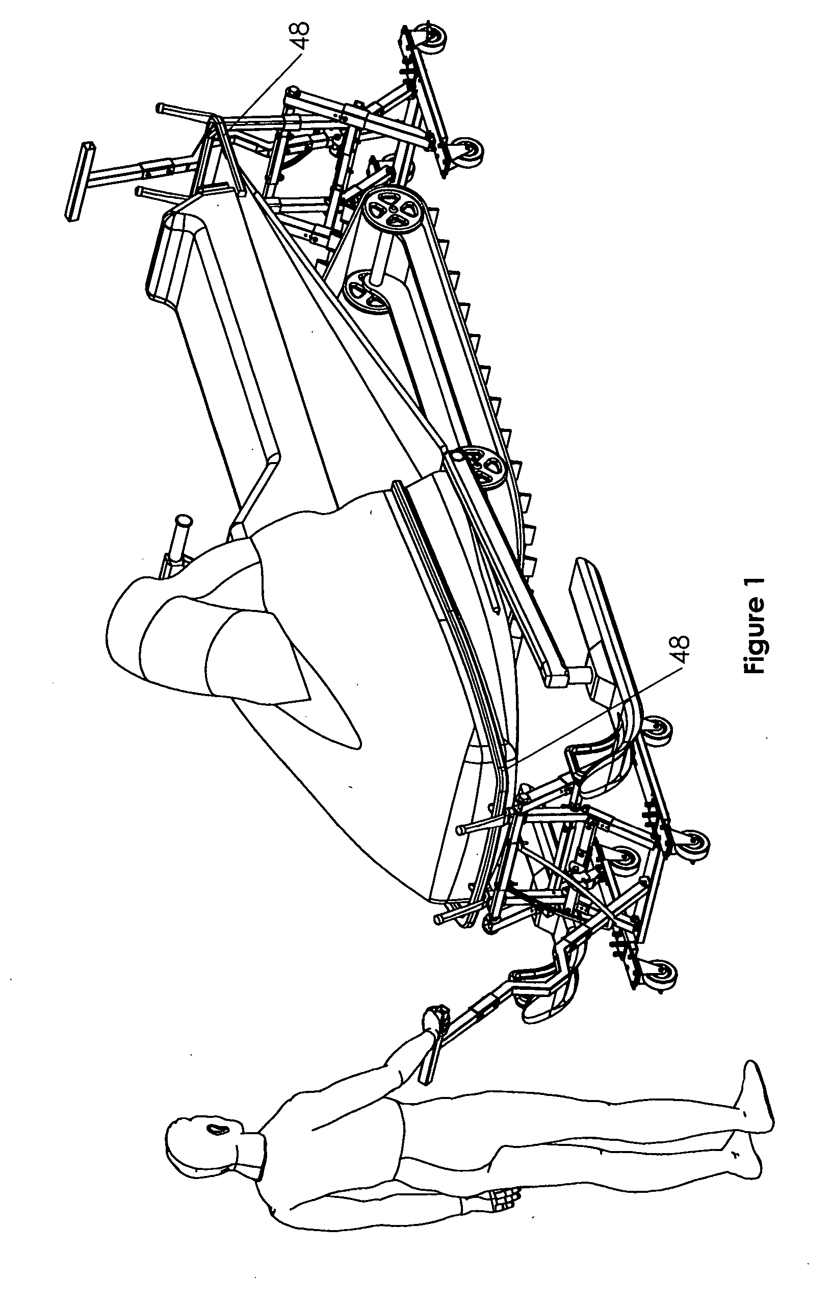
[0117]FIG. 1 is a perspective view of the lifting device of the present invention on the front and back end of a snowmobile. This figure illustrates the versatility of the present invention in that it can be used on the front and / or back end of the vehicle. The features of the present invention that make that versatility possible are illustrated in detail in the following figures.
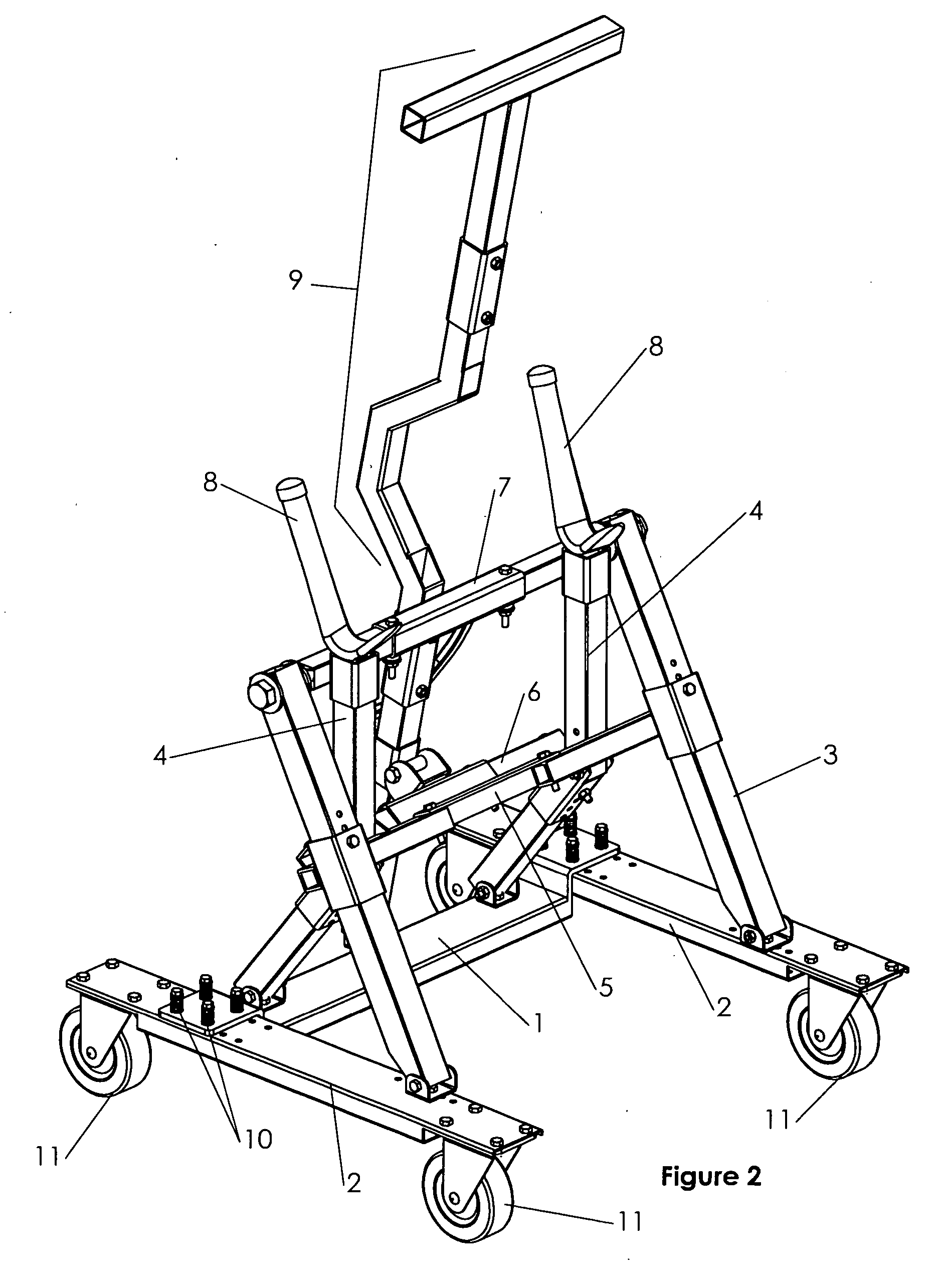
[0118]FIG. 2 is a front perspective view of the lifting device of the present invention with the handle 9 in an upright position. This figure illustrates the main components of the present invention, which are the cross-bar 1, two wheel support members 2, two first legs, two second legs 4, a first lateral member 5, a second lateral member 6, a third lateral member 7, two cradle arms 8, and a handle 9. In the preferred embodiment, the cross-bar 1 is attached to the two wheel support members 2 by a plurality of spring bolts that provide flexibility to the unit. Underneath each wheel support member 2 are two ...
PUM
 Abstract
Description
Claims
Application Information