Transmitting and receiving method, and radio apparatus utilizing the same

a technology of transmission and receiving method, applied in the field of transmission and receiving technology, can solve the problems of frequency selective fading, transmission quality and effective data rate deterioration, etc., and achieve the effect of reducing data error occurrence, reducing data interference, and reducing data ra

Active Publication Date: 2006-11-02
HERA WIRELESS
View PDF24 Cites 19 Cited by
  • Summary
  • Abstract
  • Description
  • Claims
  • Application Information

AI Technical Summary

Benefits of technology

[0012] According to this embodiment, the known signals are transmitted from a plurality of antennas when the request signal is sent to a radio apparatus to be communicated with. As a result thereof, information, on data rates, generated anew based on the known signals can be acquired, thus contributing to improving the information accuracy.
[0071] Still another preferred embodiment according to the present invention relates also to a transmitting method. This method comprises: outputting a burst signal of a plurality of streams; and generating a burst signal, to be outputted in the outputting, which contain known signals assigned respectively in a plurality of streams and data assigned posterior to the known signal. The generating includes: assigning data to a plurality of streams by increasing the number of streams to be assigned if the data is assigned in at least one of the plurality of streams; and varying a combination of subcarriers to be used respectively for the known signals, for each of a plurality of streams, while using the plurality of subcarriers for the known signals and data, and using a combination of subcarriers in the known signal assigned in the same stream as the data, for said data, when the data are assigned in the plurality of streams.

Problems solved by technology

The burst signals in such a wireless LAN are generally transmitted via a time-varying channel environment and are also subject to the effect of frequency selective fading.
If any error is contained in the rate information determined by the receiving apparatus, an error will be caused in communications by a MIMO system and therefore the transmission quality and effective data rate will deteriorate.

Method used


Image

  • Transmitting and receiving method, and radio apparatus utilizing the same
  • Transmitting and receiving method, and radio apparatus utilizing the same
  • Transmitting and receiving method, and radio apparatus utilizing the same

Examples


first embodiment

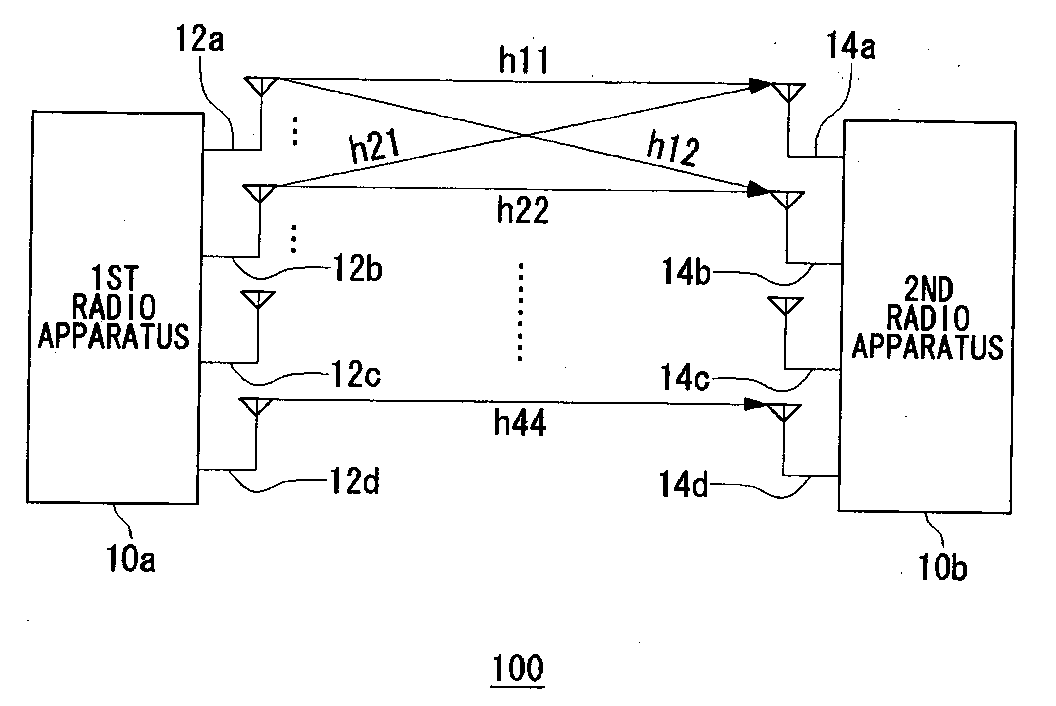
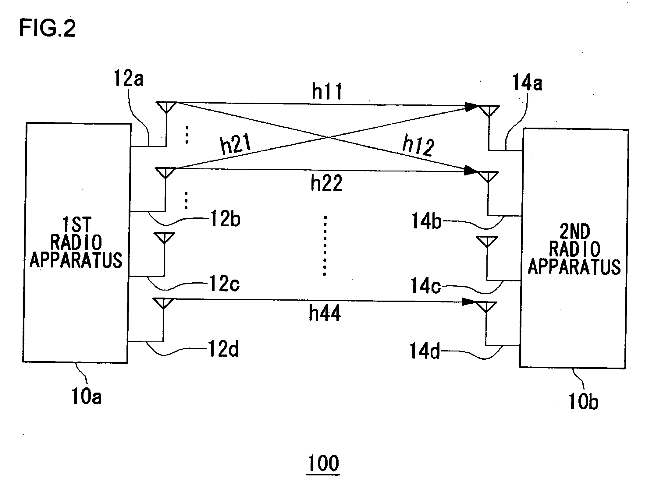
[0117] Before describing the present invention in detail, an outline of the present invention will be described first. A first embodiment of the present invention relates to a MIMO system comprised of two radio apparatuses (for convenience, hereinafter referred to as “first radio apparatus” and “second radio apparatus”). Both the first radio apparatus and the second radio apparatus carry out adaptive array signal processing. The MIMO system changes the data rate by varying the values or mode corresponding to the number of antennas, modulation scheme and coding rate of error correction. In so doing, a radio apparatus at the transmitting side transmits a rate request signal to a radio apparatus at the receiving side. For example, when the first radio apparatus transmits data to the second radio apparatus, the first radio apparatus transmits the rate request signal to the second radio apparatus.

[0118] The second radio apparatus conveys rate information of its own to the first radio ap...

second embodiment

[0202] Similar to the first embodiment, a second embodiment of the present invention relates to a MIMO system and it particularly relates to a transmitting apparatus in the MIMO system. The transmitting apparatus according to the present embodiment corresponds to transmitting functions in the first radio apparatus or second radio apparatus in the first embodiment. In the same situation as in the first embodiment where the training signals are to be transmitted, the transmitting apparatus transmits training signals. Here, a description will be given centering around a burst format containing training signals, and the repeated description on the same situation, in which the training signals are to be transmitted, as in the first embodiment is omitted. The transmitting apparatus transmits a burst signal composed of a plurality of streams, namely a burst signal of multiple streams, corresponding to a plurality of antennas and assigns a plurality of MIMO-STSs in a burst signal composed o...

third embodiment

[0215] A third embodiment of the present invention corresponds to an embodiment in which the first embodiment and the second embodiment are combined together. That is, the radio apparatus generates training signals formed by burst formats as in the first embodiment, namely, burst signals of a plurality of streams. The radio apparatus also multiplies the thus generated burst signals of a plurality of streams by a steering matrix as in the second embodiment, so as to vary and deform the burst signals of a plurality of streams. The radio apparatus transmits the thus deformed burst signals of a plurality of streams from a plurality of antennas. Here, the radio apparatus may respectively multiply MIMO-STS, MIMO-LTS and Data contained in the burst signals of a plurality of streams, by a steering matrix.

[0216] A radio apparatus 10 according to the third embodiment is of the same type as the first radio apparatus 10a of FIG. 6. The transmitting functions in the radio apparatus 10 according...


PUM


Abstract

A processing unit transmits, from at least one of a plurality of antennas, data corresponding respectively to the plurality of antennas. A control unit generates request signals with which to let a second radio apparatus supply information on rates at the second radio apparatus. When transmitting the request signal, the processing unit also transmits, from a plurality of antennas which includes antennas other than the antennas that transmit the data, known signals corresponding respectively to the plurality of antennas.

Description

BACKGROUND OF THE INVENTION [0001] 1. Field of the Invention [0002] The present invention relates to transmitting and receiving technologies, and it particularly relates to a transmitting and receiving method, in which signals are transmitted from a plurality of antennas and the signals are received by a plurality of antennas, and a radio apparatus utilizing said method. [0003] 2. Description of the Related Art [0004] An OFDM (Orthogonal Frequency Division Multiplexing) modulation scheme is one of multicarrier communication schemes that can realize the high-speed data transmission and are robust in the multipath environment. This OFDM modulation scheme has been used in the wireless standards such as IEEE802.11a / g and HIPERLAN / 2. The burst signals in such a wireless LAN are generally transmitted via a time-varying channel environment and are also subject to the effect of frequency selective fading. Hence, a receiving apparatus generally carries out the channel estimation dynamically....

Claims


Application Information

Patent Timeline
Patent Type & Authority Applications(United States)
IPC IPC(8): H04B1/02H04M1/00H04B7/02H04J99/00
CPCH04B7/0421H04L27/2647H04B7/0619H04B7/0691H04B7/0802H04B7/0842H04L1/0002H04L1/0025H04L5/0023H04L25/0204H04L25/0206H04L25/0226H04L27/2601H04L27/261H04B7/061H04L25/0224
Inventor NAKAO, SEIGO
Owner HERA WIRELESS
Why Eureka
Try Eureka