Method and apparatus for monitoring a switching process and relay module

a relay module and switching process technology, applied in the direction of instruments, code conversion, using mechanical means, etc., can solve the problems of subtle wear of the switching element, deterioration of the outer layer of the contact, and significant stress on the switching element and/or the metallic switching contacts during the switching process

Inactive Publication Date: 2010-04-01
SIEMENS AG
View PDF15 Cites 8 Cited by
  • Summary
  • Abstract
  • Description
  • Claims
  • Application Information

AI Technical Summary

Benefits of technology

[0007]It is an object of the present invention to specify a method which enables better information

Problems solved by technology

When switching the said consumer, in particular in the case of consumers with a high power requirement, in particular start-up power requirement, the switching element and/or the metallic switching contacts are put under significant stress during the switching process.
This stress results in subtle wear of the switching element.
If the switching element is embodied as a metallic contact pair, the outer layer of the contacts will deteriorate over the cours

Method used


Image

  • Method and apparatus for monitoring a switching process and relay module
  • Method and apparatus for monitoring a switching process and relay module
  • Method and apparatus for monitoring a switching process and relay module

Examples


Embodiment Construction

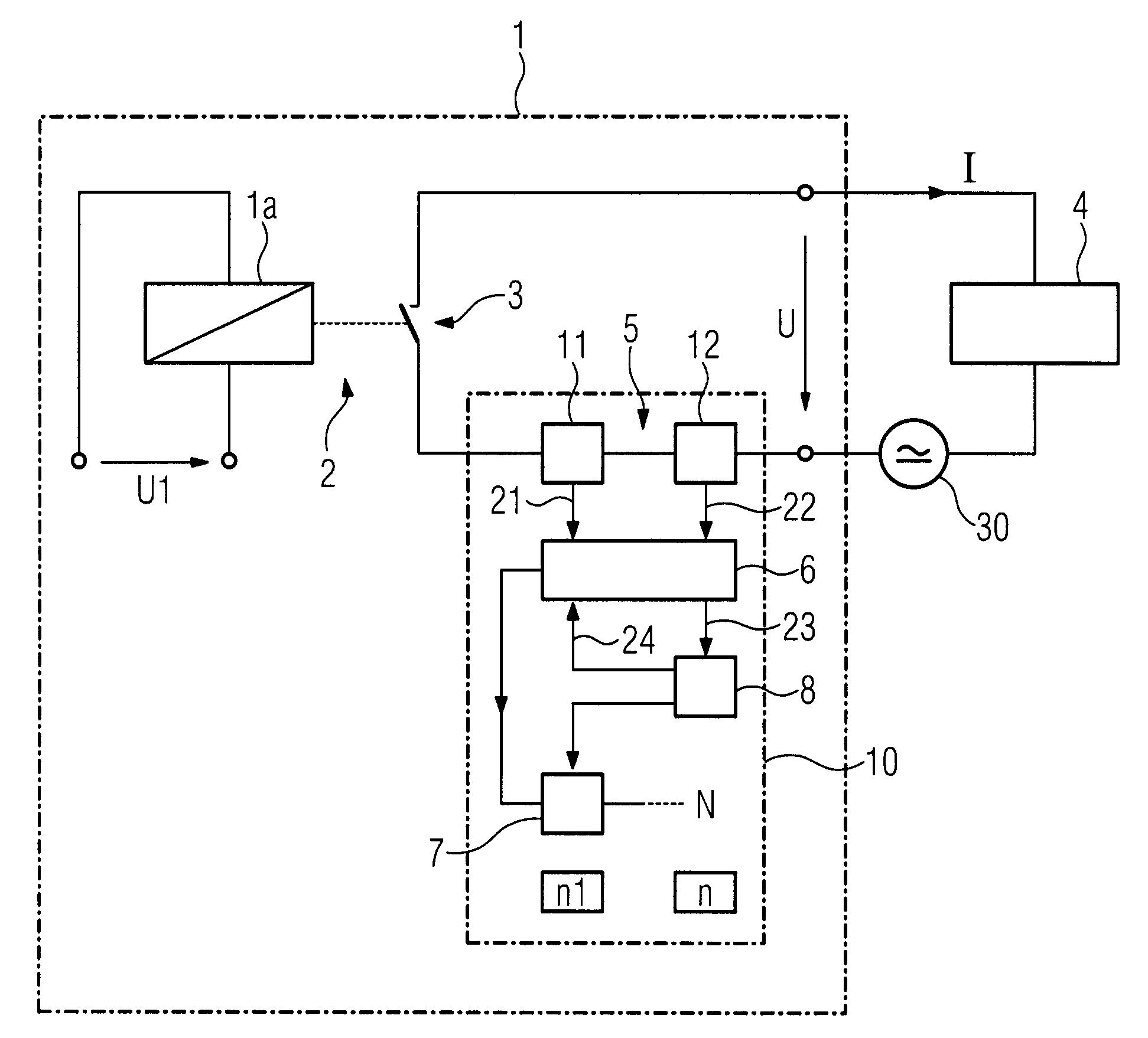
[0025]According to FIG. 1, a relay module 1 is shown, with the relay module 1 having an apparatus 10 for monitoring a switching process of a switching element 3 for switching an electrical current I for a consumer 4. The consumer 4 is connected to the relay module 1 by way of connecting terminals. A voltage source 30 is in the current circuit of the consumer 4, with the current circuit being closed by closing the switching element 3 and the voltage source 30 being able to drive a current I through the consumer 4. The voltage source 30 may be embodied as an alternating voltage source or as a direct current voltage source.

[0026]The switching element 3 is actuated by means of a relay coil 1a by way of an active connection. The relay coil 1a is excited by applying a switching voltage U1 to a first relay coil input and second relay coil input in order to switch the switching element 3. The relay coil 1a and the switching element 3 form a relay 2.

[0027]The apparatus 10 for monitoring the ...


PUM


Abstract

An apparatus for monitoring a switching process of a switching element for switching an electrical current for a consumer is provided. The apparatus includes a determination means for determining at least one individual consumption value of the consumer, a comparison means for comparing the at least one consumption value with a reference value, and a prediction means for predicting a maximum number of switching cycles as a function of the comparison result.

Description

CROSS REFERENCE TO RELATED APPLICATIONS[0001]This application claims priority of International Application No. PCT / EP2008 / 008359 filed Sep. 26, 2008, and of European Patent Office Application No. 09163275.2 EP filed Jun. 19, 2009; all of the applications are incorporated by reference herein in their entirety.FIELD OF INVENTION[0002]The invention relates to a method for monitoring a switching process of a switching element for switching an electrical current for a consumer.[0003]The invention likewise relates to an apparatus for monitoring a switching process of a switching element for switching an electrical current for a consumer.[0004]The invention also relates to a relay module with an apparatus for monitoring a switching process.BACKGROUND OF INVENTION[0005]A relay module, preferably for use in a programmable controller, can switch a consumer connected to a switching output of the relay module by means of switching elements, preferably metallically configured contacts, but also ...

Claims


Application Information

Patent Timeline
IPC IPC(8): G06F19/00
CPCG01R15/146G01R21/06H03M1/12H01H47/002H03M1/0827G01R33/091
Inventor FISCHER, PETER
Owner SIEMENS AG
Why Eureka
Try Eureka