Rotary force feedback wheels for remote control devices

Inactive Publication Date: 2005-10-18
IMMERSION CORPORATION
View PDF192 Cites 93 Cited by
  • Summary
  • Abstract
  • Description
  • Claims
  • Application Information

AI Technical Summary

Benefits of technology

[0007]The present invention is directed to an interface device which is connected to a host computer and provides a rotatable wheel having force feedback. The force feedback wheel p

Problems solved by technology

One drawback to traditional mice is that functions such as scrolling a document in a window and zooming a view displayed on the screen in or out are typically awkward to perform, since the user must use the cursor to drag a displayed scroll bar or click on displayed zoom controls.
One problem with existing mouse wheels i

Method used


Image

  • Rotary force feedback wheels for remote control devices
  • Rotary force feedback wheels for remote control devices
  • Rotary force feedback wheels for remote control devices

Examples


Embodiment Construction

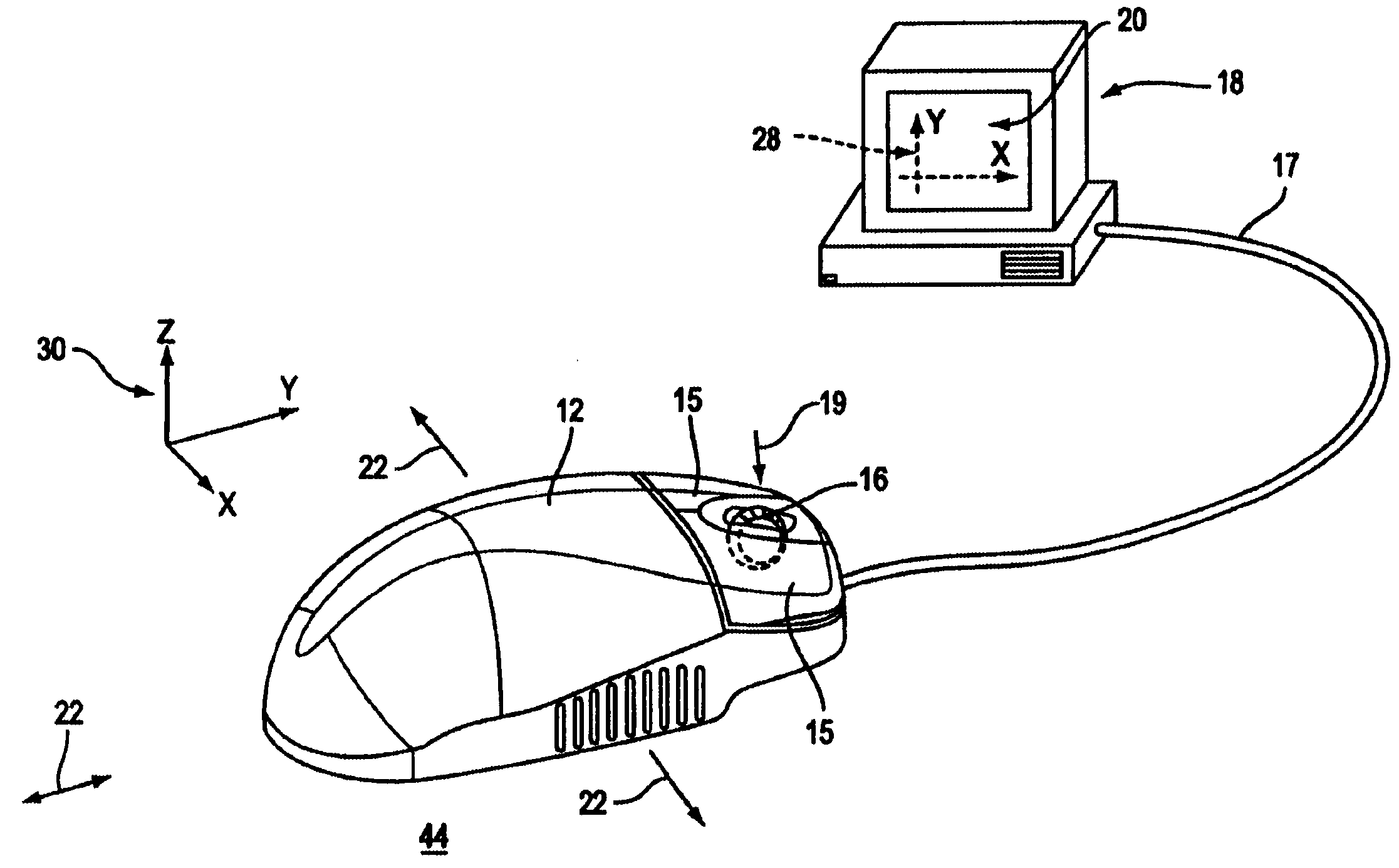
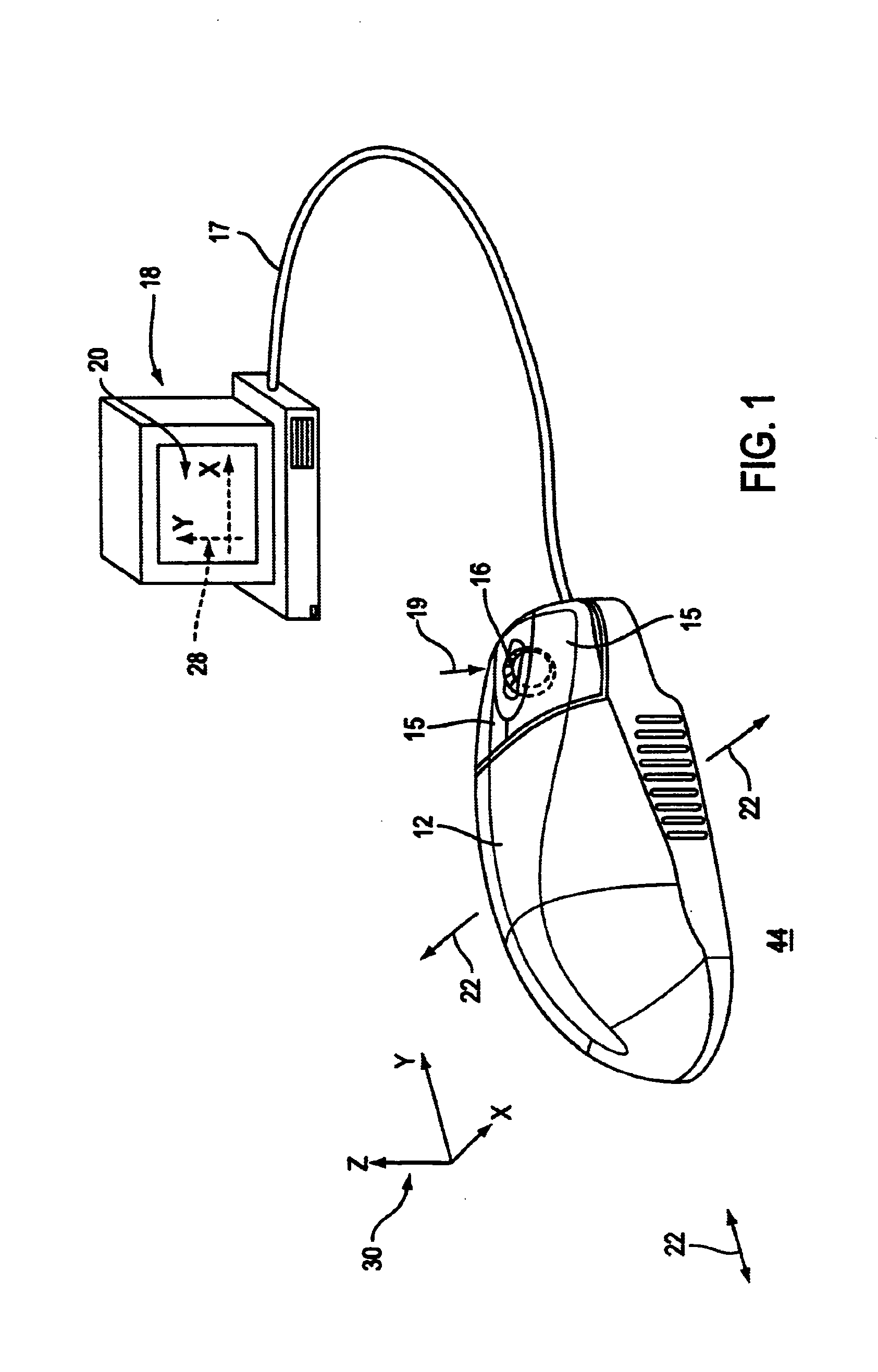
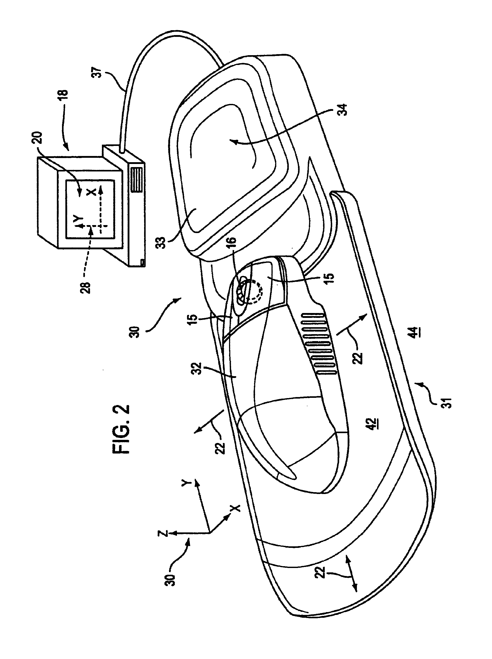
[0022]FIG. 1 is a perspective view of a mouse 12 including a force feedback mouse wheel of the present invention. Mouse 12 rests on a ground surface 44 such as a tabletop or mousepad. A user grasps the mouse 12 and moves the mouse in a planar workspace on the surface 44 as indicated by arrows 22. Mouse 12 may be moved anywhere on the ground surface 44, picked up and placed in a different location, etc. A frictional ball and roller assembly (not shown) is provided on the underside of the mouse 12 to translate the motion of the mouse 12 into electrical position signals, which are sent to a host computer 18 over a bus 17 as is well know to those skilled in the art. In other embodiments, different mechanisms can be used to convert mouse motion to position or motion signals received by the host computer. It should be noted that the term “mouse” as used herein indicates an object 12 generally shaped to be grasped or contacted by a user from above and moved within a substantially planar wo...


PUM


Abstract

A force feedback wheel is provided on a mouse or other interface device manipulated by a user. A sensor detects a position of the mouse in a workspace and sends a position signal to a connected host computer indicating that position. A rotatable wheel is mounted upon the manipulandum and rotates about a wheel axis, where a wheel sensor provides a wheel signal to the host computer indicating a rotary position of the wheel. A wheel actuator coupled to the rotatable wheel applies a computer-modulated force to the wheel about the wheel axis. The mouse can be a standard mouse or a force-feedback mouse, where forces are applied in the mouse workspace. The host computer is preferably running a graphical environment, where the force applied to the wheel can correspond with an event or interaction displayed in the graphical environment. The wheel can also be included on other devices such as remote controls and radios.

Description

[0001]This application is a continuation of application Ser. No. 09 / 049,155 filed Mar. 26, 1998 now U.S. Pat. No. 6,128,006.BACKGROUND OF THE INVENTION[0002]The present invention relates generally to interface devices for allowing humans to interface with computer systems, and more particularly to mechanical computer interface devices that allow the user to provide input to computer systems and provide force feedback to the user.[0003]Computer systems are used extensively in many different industries to implement many applications. Users can interact with a visual environment displayed by a computer on a display device to perform functions on the computer, play a game, experience a simulation or “virtual reality” environment, use a computer aided design (CAD) system, browse the World Wide Web, or otherwise influence events or images depicted on the screen. One visual environment that is particularly common is a graphical user interface (GUI). GUI's present visual images which descri...

Claims


Application Information

Patent Timeline
IPC IPC(8): G09G5/08G09G5/00G06F3/01G06F3/033
CPCG06F3/016G06F3/0354G06F2203/014
Inventor ROSENBERG, LOUIS B.SCHENA, BRUCE M.
Owner IMMERSION CORPORATION
Why Eureka
Try Eureka