

Leg type mobile robot
- Summary
- Abstract
- Description
- Claims
- Application Information
AI Technical Summary
Benefits of technology
Problems solved by technology
Method used
Image

Examples
first embodiment
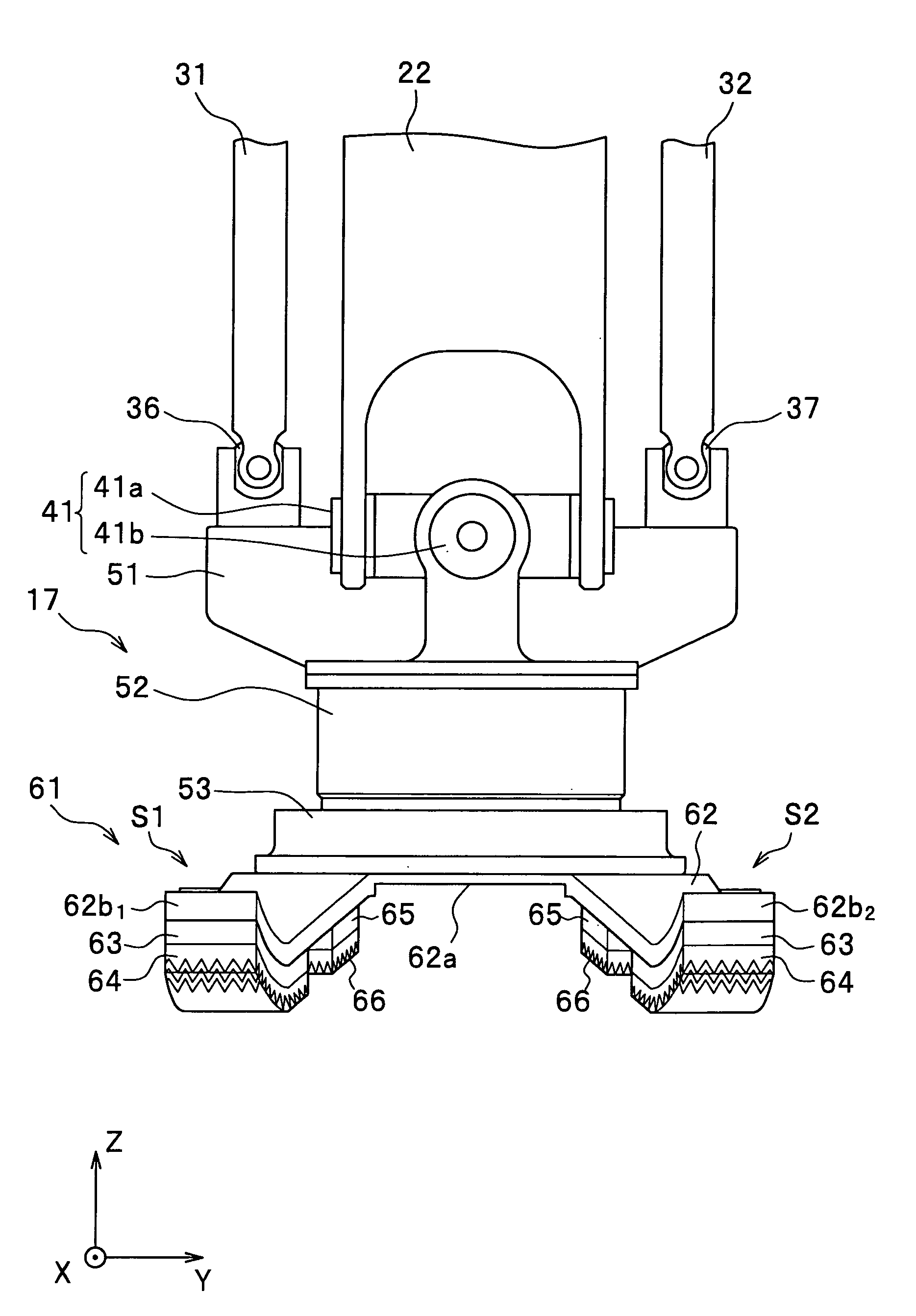
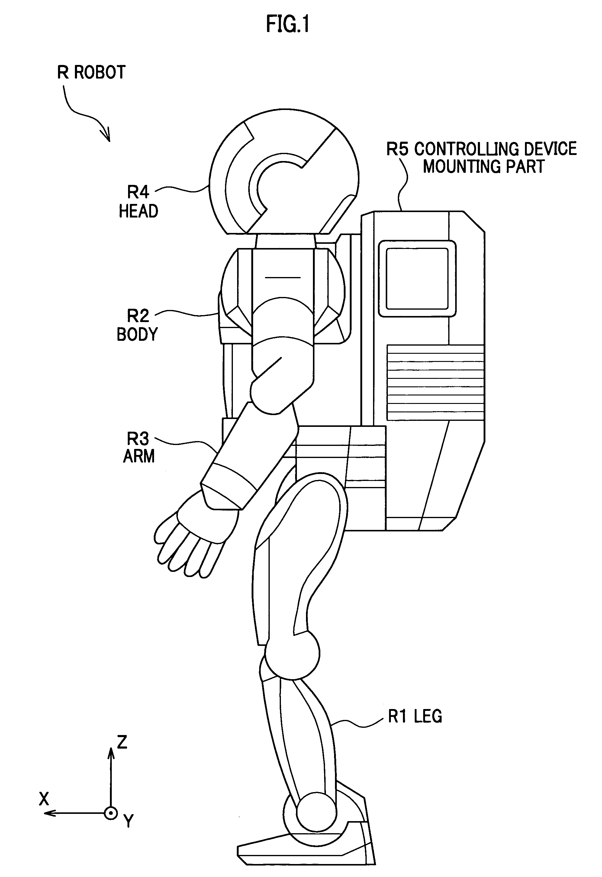
[0086] First, the foot 17 of the robot R according to the first embodiment of the present invention is described with reference to FIG. 3 to FIG. 5. FIG. 3 is a front view showing a foot of the two-feet mobile robot according to the first embodiment of the present invention. FIG. 4 is a side view showing the foot of the two-feet mobile robot according to the first embodiment of the present invention. FIG. 5 is a bottom view showing a foot of a two-feet mobile robot according to the first embodiment of the present invention. The leg R1 and the foot 17 shown in FIG. 3 to FIG. 5 are shown in a state where an armoring part of the robot R shown in FIG. 1 are suitably removed. The left leg of the robot R (the left leg R1 and the foot 17L) is shown in FIG. 3 to FIG. 5.
>
[0087] Herein, with reference to FIG. 3 and FIG. 4, the ankle joints 15 and 16 of the robot R are simply described. The ankle joints 15 and 16 of the robot R are composed by connecting a cross shaft 41 to the shank link 22 ...
second embodiment
[0129] Next, for the foot of the robot R according to the second embodiment of the present invention, different points between the first embodiment and the second embodiment are mainly described.
[0130]FIG. 10 is a side view showing the foot of the two-feet mobile robot according to the second embodiment. As shown in FIG. 10, a foot 117 according to the second embodiment is provided with a distortion detecting means 152 instead of the force sensor 52. The first base seat part 51 and the plate spring means 61 are fixed by a plurality of bolts (not shown). The distortion detecting means 152 detects the distortion of the plate spring part, particularly the distortion of the spring part 62b. Since the distortion of the plate spring part correlates with the floor reaction force inputted into the plate spring part, the floor reaction force can be detected by detecting the amount of the distortion of the plate spring part.
[0131] The amount of the distortion detected is transmitted to the ...
third embodiment
[0134] Next, for the foot of the robot R according to the third embodiment of the present invention, different points between the first embodiment and the third embodiment are mainly described.
[0135]FIG. 11 is a side view showing the foot of the two-feet mobile robot according to the third embodiment.
[0136] As shown in FIG. 11, a foot 217 according to the third embodiment is provided with a foot flat member 261 multilayered instead of the foot flat member 61.
[0137] The foot flat member 261 is provided with a plurality of multilayered plate spring bodies 262 and 262, and a viscous member 265 interposed between the plate spring bodies 262 and 262. That is, the foot 217 is composed by a spring part 262b, the viscous member 265 and the spring part 262b sequentially from above. The foot 217 is provided with multilayered plate spring parts S21 to S24 (only S22 and S24 are shown), and can attenuate the vibration of the plate spring parts S21 to S24 at the time of being grounded by the v...
PUM
 Abstract
Description
Claims
Application Information