Control Circuit For LED Backlighting

a technology of control circuit and led backlighting, which is applied in the direction of electroluminescent light sources, electric lighting sources, and use of semiconductors. it can solve the problems of high charging current, complex and expensive control circuits of this kind, and achieve simple construction, low cost, and adequate current balancing

Inactive Publication Date: 2013-11-07
MINEBEAMITSUMI INC
View PDF4 Cites 8 Cited by
  • Summary
  • Abstract
  • Description
  • Claims
  • Application Information

AI Technical Summary

Benefits of technology

[0011]According to the invention, the control unit is designed such that if all the dimming signals are logical ON, the output voltage of the PFC is regulated with the aid of the current measuring device such that the current on the primary side corresponds to a pre-determined setpoint value and that as soon as at least one dimming signal is logical OFF, the output voltage of the PFC is set to a pre-determined constant value. This makes it possible to achieve adequate current balancing in the individual control channels with little extra effort and expense in terms of circuitry. The circuit according to the invention can thus be simply constructed at low cost.

Problems solved by technology

A control circuit of this kind, however, is complex and expensive.
Current limitation is very important in this circuit arrangement since on switching the light emitting diode strings, and particularly during the initial switching on of the power supply, very high charging currents occur.

Method used


Image

  • Control Circuit For LED Backlighting
  • Control Circuit For LED Backlighting
  • Control Circuit For LED Backlighting

Examples


Embodiment Construction

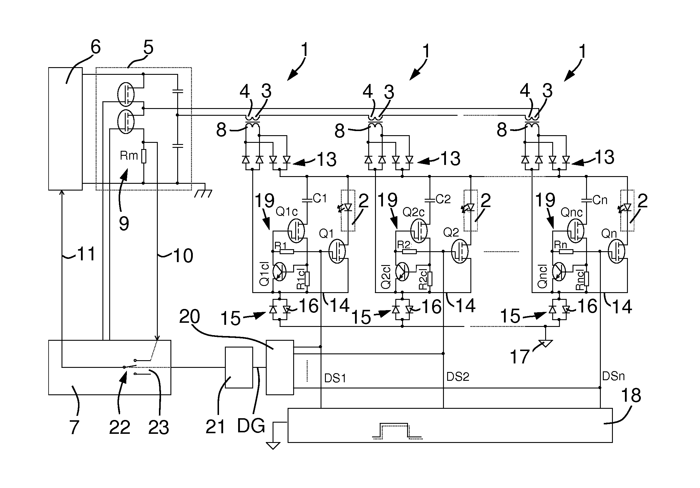
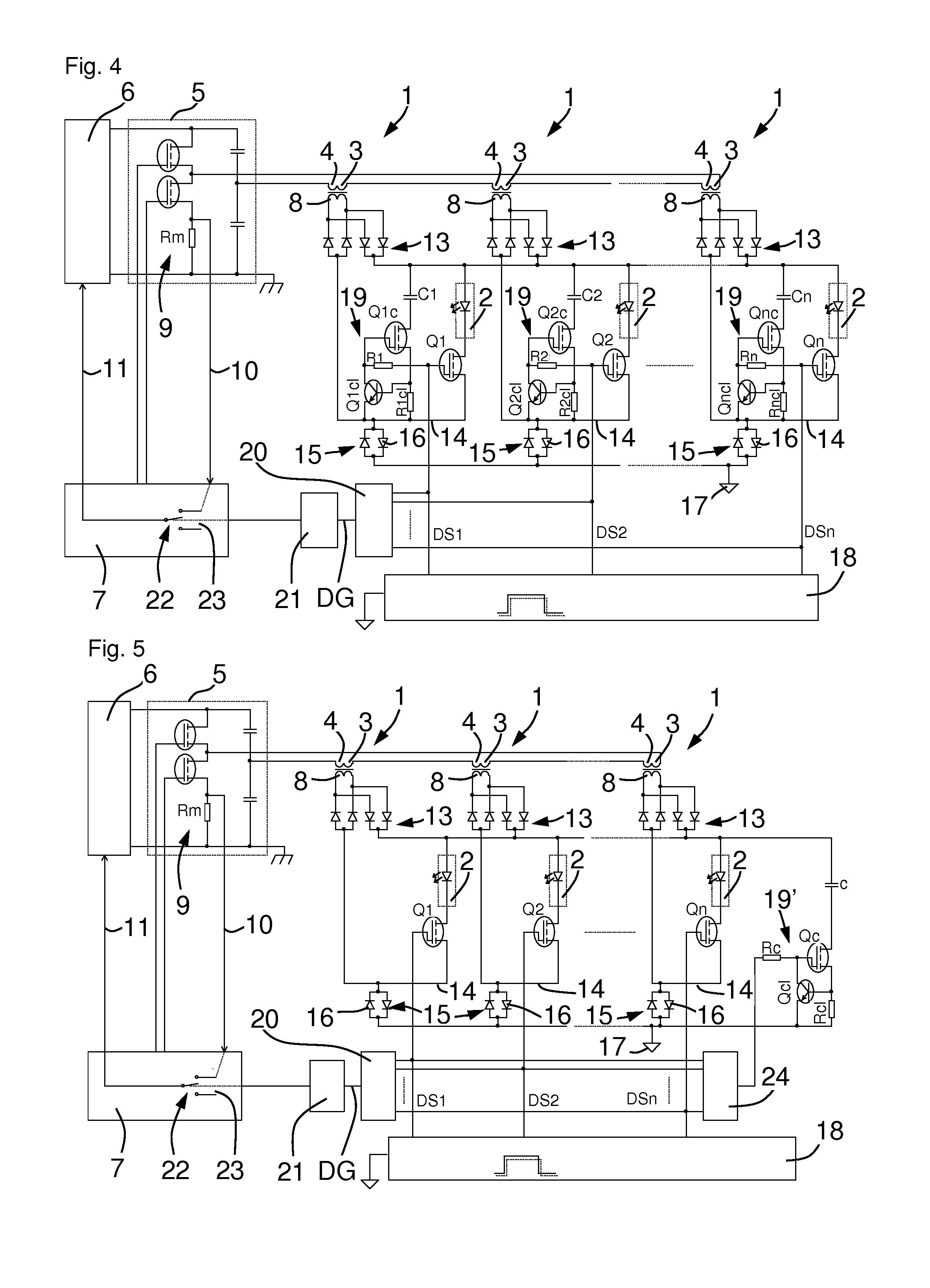
[0026]FIG. 4 shows a first embodiment of a control circuit. The control circuit has a power factor correction circuit (PFC) 6 as its DC voltage source. The regulated DC voltage of the PFC 6 is converted in a downstream bridge circuit 5 to a high-frequency AC voltage. In the example, a half bridge is illustrated. The circuit may, however, also have a full bridge or some other inverter.

[0027]The clock frequency of the AC voltage is usually about 100 kHz. However, the frequency may be nearly arbitrarily varied according to the requirements of the application.

[0028]The bridge circuit has two switches that are controlled by a control unit 7.

[0029]The control circuit has furthermore a current measuring device 9 that monitors the overall current on the primary side. For this purpose, a measuring resistor Rm is disposed in the bridge circuit 5 in this example. The voltage drop at the measuring resistor Rm is a measurement for the current that flows through the half bridge 5.

[0030]The curren...


PUM


Abstract

The invention describes a control circuit for backlighting having a plurality of control channels in each of which a light emitting diode string is controlled. The control circuit has a balancing device for balancing the currents in the individual control channels, and a control unit that is connected to a power factor correction circuit (PFC), to a bridge circuit and to a primary-side current measuring device. Each control channel has a switch for switching the light emitting diode string that is connected to a separate dimming signal. The control circuit furthermore has at least one smoothing capacitor and one current limiter that limits the charging current for the smoothing capacitor. The control unit is additionally designed such that if all the dimming signals are logical ON, the output voltage of the PFC is regulated with the aid of the current measuring device such that the current on the primary side corresponds to a pre-determined setpoint value and that as soon as at least one dimming signal is logical OFF, the output voltage of the PFC is kept constant at its last value (FIG. 4).

Description

FIELD OF THE INVENTION[0001]The invention describes a control circuit for light emitting diodes having a plurality of control channels and a balancing device for balancing the currents in the individual control channels, having a control unit that is connected to a power factor correction circuit or respectively a power factor correction controller (PFC), to a bridge circuit and to a current measuring device on the primary side.BACKGROUND OF THE INVENTION[0002]Flat-screen televisions and monitors having liquid crystal displays require backlighting. This backlighting is being increasingly realized using light emitting diodes (LED) rather than cold cathode tubes since LEDs need less energy and have a longer useful life. In FIG. 1, a television 27 having this kind of backlighting is outlined. The light emitting diodes 12 are disposed here in a plurality of light emitting diode strings 2 (LED string) at the upper and lower edges of the television screen 27. In the example, two light emi...

Claims


Application Information

Patent Timeline
Patent Type & Authority Applications(United States)
IPC IPC(8): H05B33/08H05B44/00
CPCH05B33/0806H05B33/0827H05B33/0815Y02B20/348H05B45/46Y02B20/30H05B45/355H05B45/327H05B45/39
Inventor WEGER, ROBERTRAYKHMAN, MYKHAYLO
Owner MINEBEAMITSUMI INC
Why Eureka
Try Eureka