Hydraulic circuit for torsional damper assembly of an electrically variable transmission

a technology of torsional damper and electrically variable transmission, which is applied in the direction of friction lining, coupling, gearing, etc., can solve the problems of undesirable torsionals or vibrations of automobile engines, undesirable vibrations, etc., and achieve the effect of reducing or eliminating compression pulses and torsionals

Inactive Publication Date: 2007-05-29
CHRYSLER GROUP LLC
View PDF15 Cites 7 Cited by
  • Summary
  • Abstract
  • Description
  • Claims
  • Application Information

AI Technical Summary

Benefits of technology

[0008]More specifically, the present invention provides an electrically variable transmission with at least one electric motor and a rotatable torsional damper assembly. The torsional damper assembly includes a torsional spring operable to eliminate or reduce compression pulses and torsionals. A clutch assembly is further provided, having a hydraulically operable piston for selectively locking out the torsional spring; whereas at least one electric motor cancels out compression pulses when the torsional spring is locked out. Also included is a hydraulic fluid applicable to opposing sides of said piston to sufficiently hydraulically balance the piston so as to prevent the clutch assembly from locking out the torsional spring at least partially in response to centrifugal forces resulting from the rotational speed of the damper.
[0009]Also provided is a method of operating a rotatable hydraulically actuated torsional damper of an electrically variable transmission in the start, stop and drive modes. The method includes hydraulically locking out the torsional damper during the start and stop modes with hydraulic fluid; and hydraulically counter balancing the lockout piston of the torsional damper to prevent the hydraulically locking out of the torsional damper during drive mode.

Problems solved by technology

Automobile engines produce torsionals or vibrations that are undesirable to transmit through the vehicle transmission.
Compression pulses are generated by the engine during starts and stops that can produce undesirable vibration in hybrid vehicles such as those having an electrically variable transmission.

Method used


Image

  • Hydraulic circuit for torsional damper assembly of an electrically variable transmission
  • Hydraulic circuit for torsional damper assembly of an electrically variable transmission
  • Hydraulic circuit for torsional damper assembly of an electrically variable transmission

Examples


Embodiment Construction

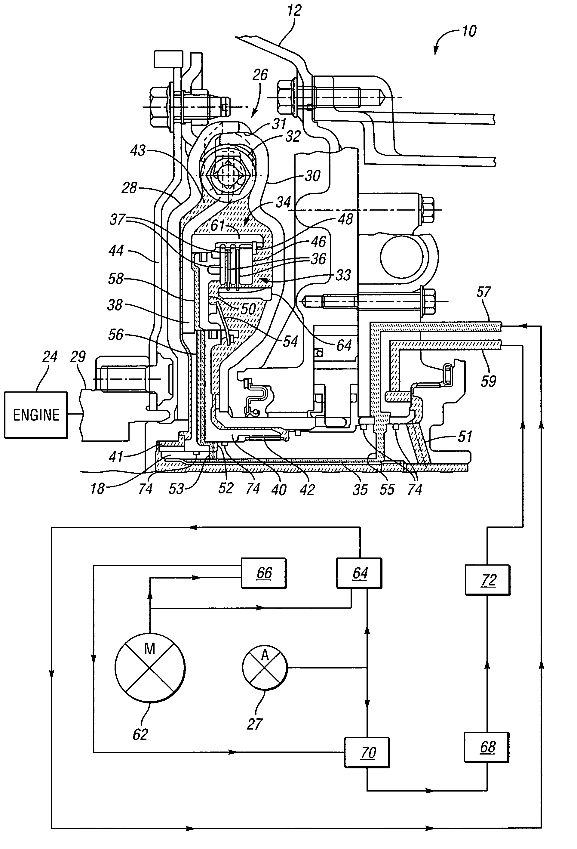
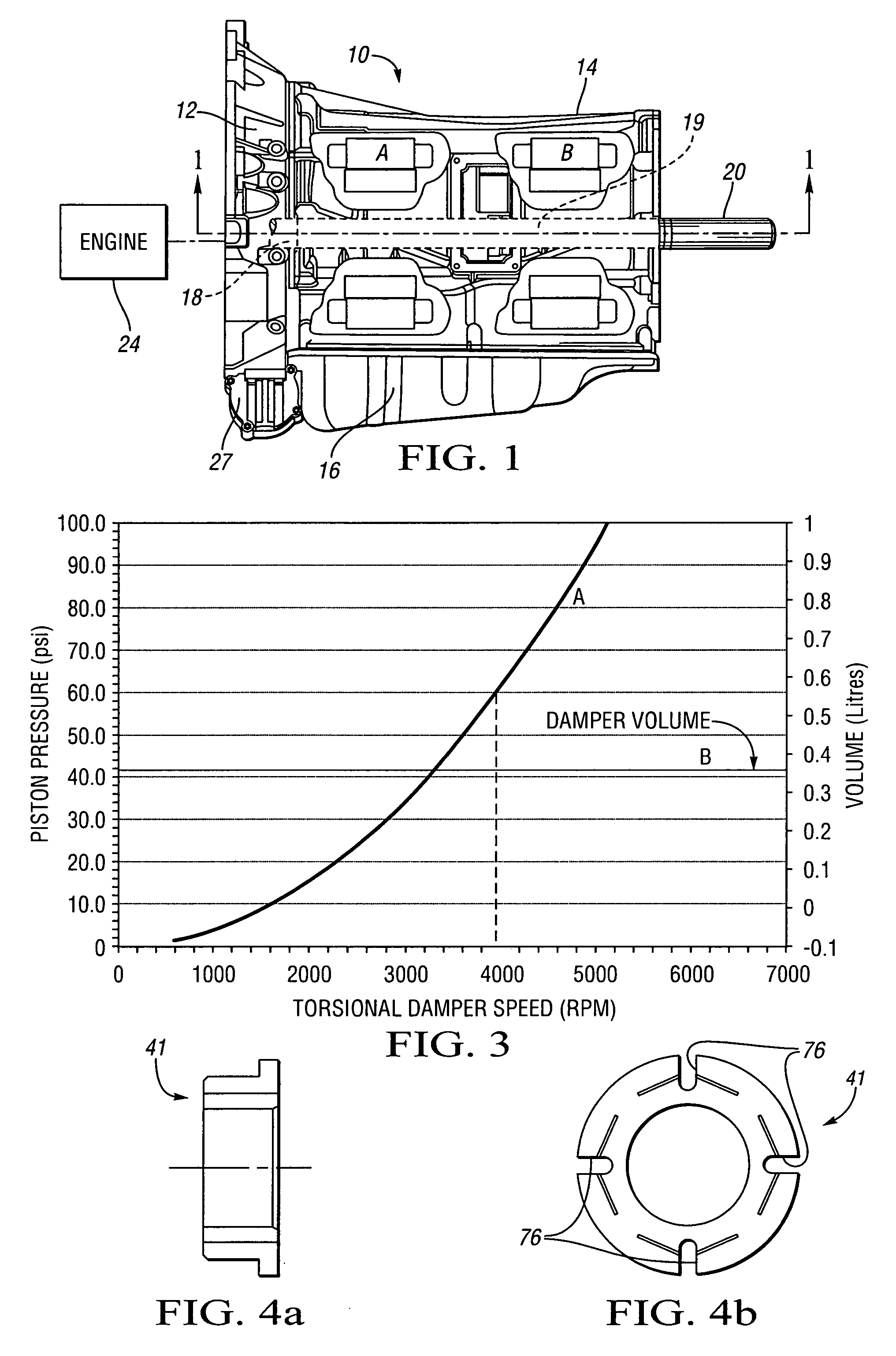
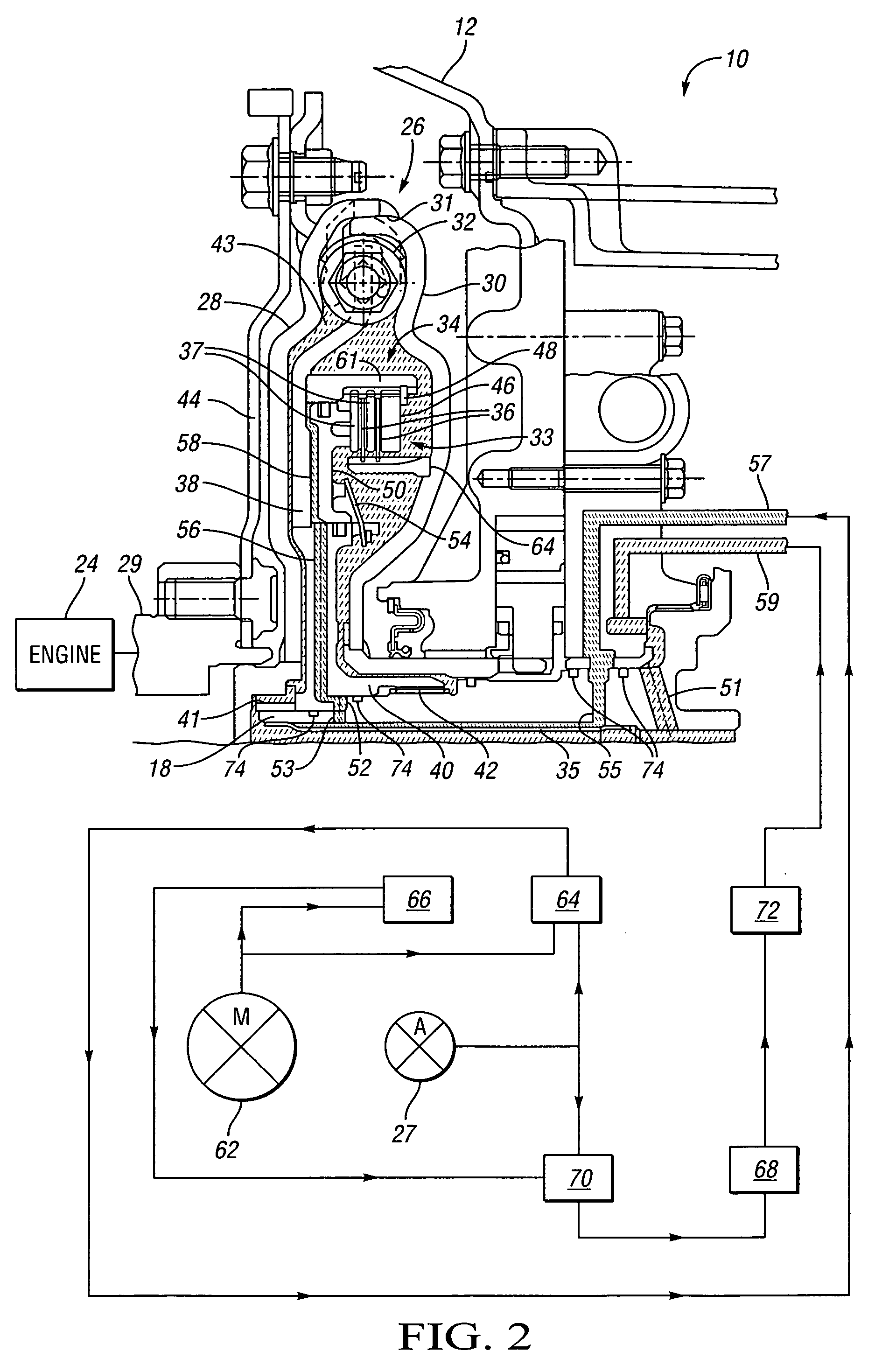
[0016]Referring to the drawings, FIGS. 1 through 2, wherein like characters represent the same or corresponding parts throughout the several views there is shown in FIG. 1 a side view of an electrically variable transmission 10. Fundamentally, the present invention is implemented in an electrically variable transmission 10 with at least one electric motor (A or B) and a rotatable torsional damper assembly 26, as shown in FIG. 2. The torsional damper assembly 26 includes a torsional spring 32 operable to eliminate or reduce compression pulses and torsionals. A clutch assembly (or lock-out clutch 33) is further provided, having a hydraulically operable piston 50 for selectively locking out the torsional spring 32; thereby enabling one or both of the electric motors (A or B of FIG. 1) to cancel out engine compression pulses. Also included is a hydraulic fluid which is applicable to the piston cavity 58 and the damper vessel 34, which are on opposing sides of the piston 50, to sufficien...


PUM


Abstract

The present invention relates to a torsional damper for an electrically variable transmission. The torsional damper is equipped with a hydraulically actuable lock-out clutch to selectively directly couple the engine to the input shaft of the transmission. The electric motors provided with the electrically variable transmission can serve to effectively cancel out engine compression pulses when the springs of the torsional damper are locked out. During higher speeds the centrifugal loading placed on oil in the torsional damper increases, which may cause the lock-out clutch to inappropriately engage. The present invention hydraulically balances the hydraulic actuator (or piston) driving the lock-out clutch to appropriately regulate lock-out clutch engagement.

Description

CROSS-REFERENCE TO RELATED APPLICATIONS[0001]This application claims the benefit of U.S. Provisional Application 60 / 555,141 filed Mar. 22, 2004, which is hereby incorporated by reference in its entirety.TECHNICAL FIELD[0002]The present invention relates to an electrically variable transmission with a torsional damper assembly having a hydraulically balanceable lock-out clutch assembly.BACKGROUND OF THE INVENTION[0003]Automobile engines produce torsionals or vibrations that are undesirable to transmit through the vehicle transmission. To isolate such torsionals, torsional dampers can be implemented into the vehicle transmission. These dampers rest between the engine crankshaft and the input shaft or turbine shaft of the transmission to substantially counteract the unwanted torsionals generated by the engine. Dampers are configured with springs that have the capacity to carry maximum engine torque plus some margin above.[0004]One premise behind hybrid automobiles is that alternative p...

Claims


Application Information

Patent Timeline
Patent Type & Authority Patents(United States)
IPC IPC(8): B60W30/20F16D3/14F16F15/131
CPCF16F15/13135F16H57/04Y10T477/26
Inventor TRYON, ERIC S.MOWATT, JOEL E.SCHOCH, KENNETH D.
Owner CHRYSLER GROUP LLC
Why Eureka
Try Eureka