Container having sliding support members

a technology of support member and container, which is applied in the field of containers, can solve the problems of unsatisfactory access and removal of parts from containers, difficult and time-consuming removal of parts therein, and stress or strain on the line worker, and achieves the effect of convenient access and efficient and safe removal

Inactive Publication Date: 2006-11-09
BRADFORD CO
View PDF21 Cites 14 Cited by
  • Summary
  • Abstract
  • Description
  • Claims
  • Application Information

AI Technical Summary

Benefits of technology

[0016] The container of the present invention is adapted so that an operator located at the front of the container may pull product to be emptied from the rear of the container forwardly to a more ergonomically friendly position after a row of products suspended by and contacting the two forward most support members, named proximal and medial support members for purposes of this document, have been unloaded or removed. Thus, a person unloading the container from the front or proximal location of the container will not have to stretch or reach to the back of the container to unload remaining product.
[0017] Similarly, a person loading the container from the front of the container need not stretch or reach to the back of the container to insert or load product into the container. The loader of the container may push the support members already loaded with rows of product rearwardly and load additional product in a more ergonomically friendly position or manner. For example, after a row of products is loaded between two support members, i.e. a distal or first and second or medial support member, these support members are pushed rearwardly to enable the loader to load an additional row of product between the medial support member and a third or proximal support member. Thus, the present invention allows product to be more efficiently and safely removed from these containers or inserted therein without unnecessary stress or strain on the unloader or loader.
[0018] Moreover, because the product receptacles are located at or near the top of the support members, products may be easily accessed. In otherwords, the product receptacles keep the product in an optimum location for removal by an unloader or insertion by a loader.
[0020] In alternative embodiments of the present invention, a plurality of tracks or retainers are attached to the body of a container at different heights whereby multiple layers or levels of product may be shipped in a single reusable and returnable container. This allows for maximizing the number of parts which may be shipped in a container, as well as ensuring that the product will be able to be moved to an ergonomically friendly area or zone within the container prior to its removal by an unloader and / or insertion by a loader. For example, once an upper layer of product is removed, all the support members of the upper layer may be pushed to the rear of the container thus exposing a lower layer of product residing on a lower set of slidable support members. The lower layer of product may be removed and the lower support members continually moved toward the unloader to insure that the lower layer of product remains as close as possible to the unloader prior to it being unloaded. Similarly, once a lower layer of products is loaded or inserted into the container, another upper layer of products may be loaded in a manner which does not cause unnecessary stress or strain on the body of the individual loading the container. The container of the present invention is not limited to two layers, the container may have any number of such layers.
[0022] Similarly, product may be easily and quickly loaded into a reusable and returnable container using the present invention. A loader first loads product so that the product is suspended between opposing product receptacles, the first product receptacle being located in a distal support member and the second product receptacle being located in a medial support member. Once a row of product has been suspended between the distal and medial support members, the distal and medial support members are rolled or moved away from the loader so that another row of products may be loaded into the receptacles of the next two support members, a proximal support member and the medial support member. The loader then inserts the next row of product so that it is suspended between product receptacles of the proximal and medial support members. Once all the product in this row is inserted, the proximal and medial support members are rolled or moved away from the loader, i.e., to the rear of the container. If the container contains additional support members, the process continues until all support members of the container have been loaded with product being suspended therefrom.

Problems solved by technology

Some existing containers are difficult to access which makes removal of the parts therein difficult and time consuming.
Any delay in access and removal of the part from the container is undesirable.
The size and / or weight of the parts or work pieces may cause stress or strain on the line worker, and more particularly on the back of the worker when inserting or removing parts from such a container.
Such ergonomically unfriendly movements may cause physical trauma, pain, and other injuries that may lead to lost production time.
This requires space around the container which may not be available, depending on the physical layout of the plant or facility.
The length (front to back) of certain containers may be limited because the container manufacturer needs to eliminate the need for a line worker to walk around the container to remove product from inside the container.
The more containers need to ship a predetermined number of parts, the greater the cost to the shipper.
This movement by the line worker is ergonomically unfriendly because the line worker must lean forward and bend down into the container to insert or remove a part or work piece from the bottom of the container.
Depending upon the number of times the line worker repeats this unnatural motion into the interior of the container, strain in the back, legs and arms may result.
The size and / or weight of the parts or work pieces may increase the strain on the line worker.
Thus, simply removing multiple parts during a work day may cause physical trauma, pain, and other injuries that may lead to lost production time.

Method used


Image

  • Container having sliding support members
  • Container having sliding support members
  • Container having sliding support members

Examples


Embodiment Construction

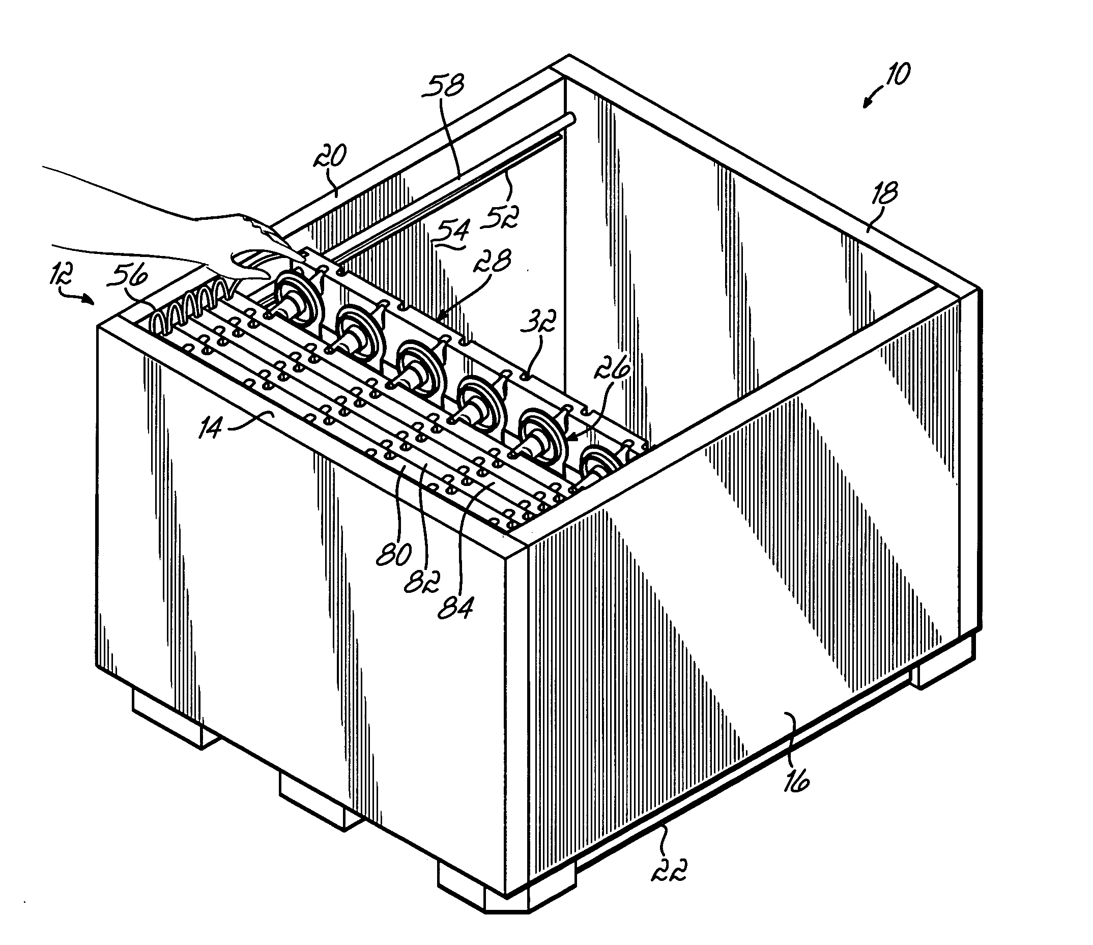
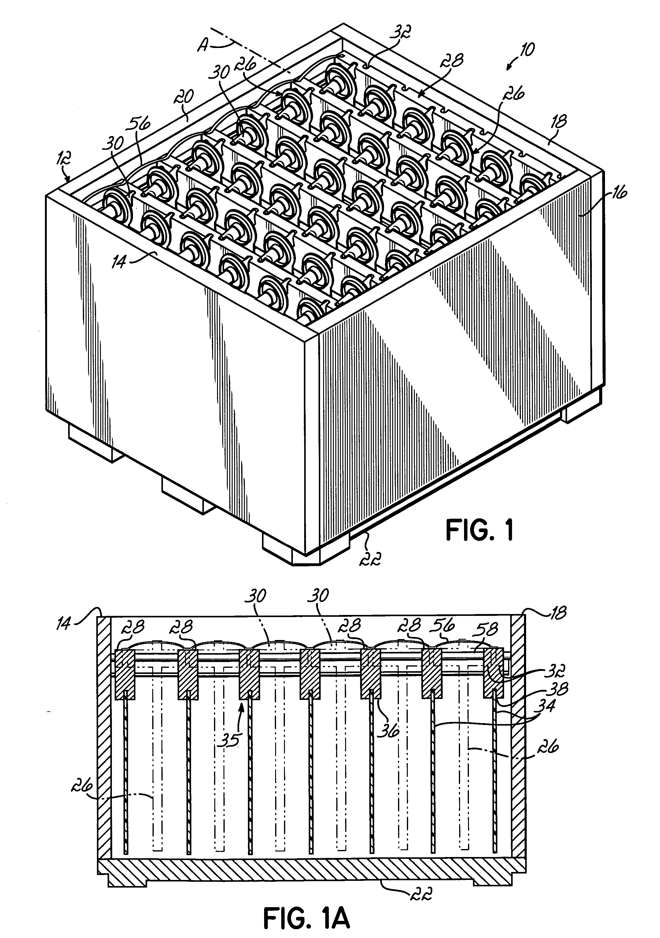
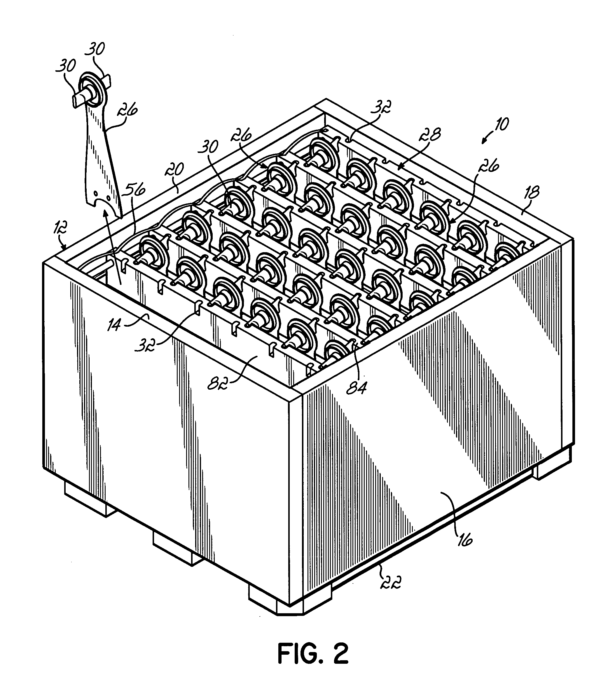
[0039] Referring to FIG. 1, there is illustrated a reusable and returnable container 10 according to one embodiment of the present invention. The reusable and returnable container 10, as shown, comprises a body 12 having a front wall 14, a side wall 16, a rear wall 18 and another side wall 20, all extending upwardly from a base 22. Although one type of container is illustrated, the present invention may be used with any type or configuration of box or container. For example, the present invention may be used in a container in which one or more of the walls of the container is hinged for the container to be more easily erected and / or compacted for storage. The present invention may also be used in a rack type of container which has four corner posts extending upwardly from a base. A cover (not shown) may also be included to enclose the container 10 and further protect and secure product 26 during shipment.

[0040] Products 26 are suspended by and supported by a plurality of support me...


PUM


Abstract

The present invention provides a container for holding product therein during shipment and being returned for reuse that has a body, tracks attached to opposite sides of the body, and a plurality of support members supported by the tracks. Rollers are located at the ends of the support members which roll in the tracks to move the support members. The support members have product receptacles whereby products may be suspended between adjacent support members, portions of the products residing in the product receptacles.

Description

FIELD OF THE INVENTION [0001] The present invention relates to containers for use in shipping, and more particularly, to containers with movable members for supporting product. BACKGROUND OF THE INVENTION [0002] A large number of different container structures are utilized by manufacturers to ship a variety of different products to end users, which may be, for example, assembly plants. In the automobile industry for example, an assembly plant assembling a particular automobile might utilize a number of different parts from different manufacturers. These manufacturers ship their respective parts to the assembly plant in container structures where the parts are then removed from dunnage or support members inside the container structure and assembled into a finished automobile. [0003] Access to the product in the containers is of particular concern. Specifically, in the automotive industry, the containers full of product are positioned on an assembly line adjacent to a work area which ...

Claims


Application Information

Patent Timeline
Patent Type & Authority Applications(United States)
IPC IPC(8): B65D73/00
CPCB65D19/06B65D2519/00338B65D2519/00587B65D2519/00621B65D2519/00646B65D2585/6887B65D2519/00805B65D2519/0082B65D2519/009B65D2585/6882B65D2519/00666
Inventor NYEBOER, CALVIN D.FEENSTRA, MARK J.
Owner BRADFORD CO
Why Eureka
Try Eureka