Stabilizer control unit

a control unit and stabilizer technology, applied in the direction of interconnection systems, resilient suspensions, vehicle springs, etc., can solve the problem of always tilting the front of the vehicle in the left or the right direction, and achieve the effect of ensuring the stability of the vehicl

Inactive Publication Date: 2006-11-09
AISIN SEIKI KK
View PDF6 Cites 22 Cited by
  • Summary
  • Abstract
  • Description
  • Claims
  • Application Information

AI Technical Summary

Benefits of technology

[0006] With this configuration, even in the event that the irregularity has occurred that one of the first stabilizer bar and the second stabilizer bar is stuck in a contorted state so that a rolling moment in one direction acts on the vehicle, it is possible to compensate the rolling moment acting on the vehicle between the first stabilizer bar and the second stabilizer bar and it can be avoided that the vehicle tilts to the left or right. Thus, the stability of the vehicle can be ensured.
[0008] With this configuration, even in the event that the irregularity occurs that one of the first stabilizer bar and the second stabilizer bar is stuck in a contorted state, the other of the first stabilizer bar and the second stabilizer bar in the vehicle is driven to be contorted in a way that the tilting of the chassis of the vehicle is suppressed, so that it can be avoided that the vehicle tilts to the left or right. Thus, the stability of the vehicle can be ensured.
[0010] With this configuration, the control to avoid tilting of the vehicle is performed by matching the amount of driving of the first stabilizer bar or the second stabilizer bar where the irregularity was detected. Therefore it is possible to ensure stability even better.
[0014] With this configuration, even in the case that the irregularity occurs that the first stabilizer bar disposed at either the front wheels or the rear wheels of the vehicle is stuck in a contorted state that lets a rolling moment in one direction act on the vehicle, a rolling moment in the other direction is applied to the second stabilizer bar disposed at the other of the rear wheels and the front wheels, resisting the rolling moment from the one direction, so that it is possible to avoid a state in which the vehicle tilts to the left or right. Therefore it is possible to ensure the stability of the vehicle.
[0016] With this configuration, even in the event that the irregularity occurs that the first stabilizer bar disposed at the front wheels or the rear wheels of the vehicle is stuck in a contorted state, the second stabilizer bar attached at the other of the front and rear wheels is driven such that tilting of the chassis of the vehicle is suppressed, so that it is possible to avoid a state in which the vehicle tilts to the left or right. Therefore it is possible to ensure the stability of the vehicle.
[0052] As described above, in case that an irregularity occurred, such as that the frontward stabilizer bar 25 is stuck in a contorted state as shown in FIG. 6 so that a rolling moment to the left acts on the vehicle 1, the stabilizer control apparatus 10 controls, with the ECU 50, the rearward stabilizer bar 35 such that it applies to the vehicle 1 a rolling moment to the right. That means that between the frontward stabilizer bar 25 and the rearward stabilizer bar 35 of the vehicle 1, the rolling moment acting on the vehicle 1 is canceled. Therefore, it can be avoided that the vehicle 1 assumes a tilted state, even in a case where either the frontward stabilizer bar 25 or the rearward stabilizer bar 35 of the vehicle 1 is stuck in a contorted state. As a result, the stability of the vehicle 1 can be ensured.

Problems solved by technology

However, in this conventional stabilizer control apparatus, there is the risk that the vehicle front stays always tilted in the left or the right direction when the turning actuator is stuck while the stabilizer disposed at the front wheels of the vehicle is contorted (even though it is not necessary to apply a resisting moment to the vehicle).

Method used


Image

  • Stabilizer control unit
  • Stabilizer control unit
  • Stabilizer control unit

Examples


Embodiment Construction

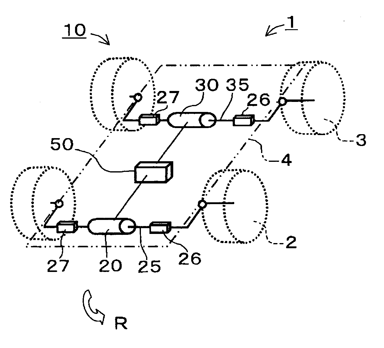
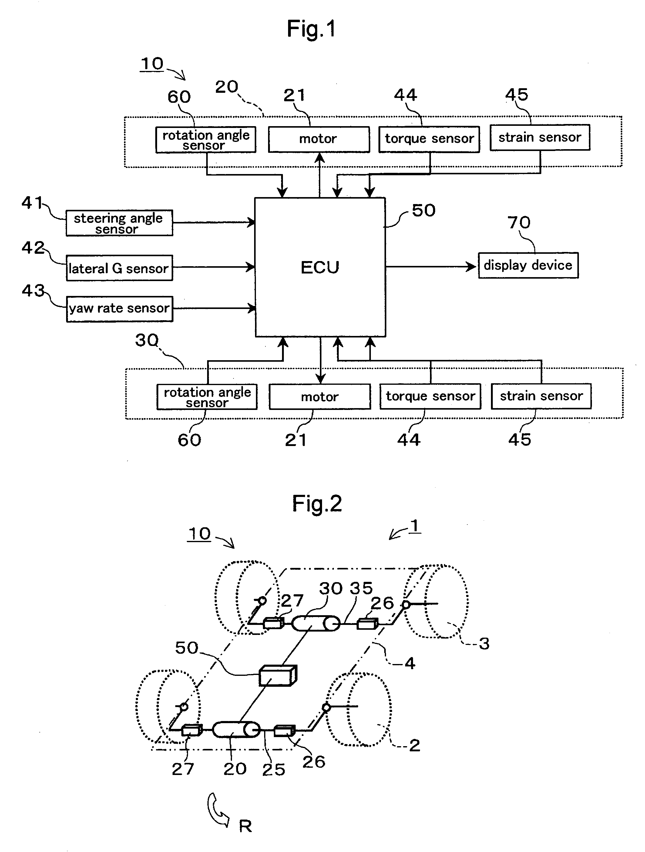
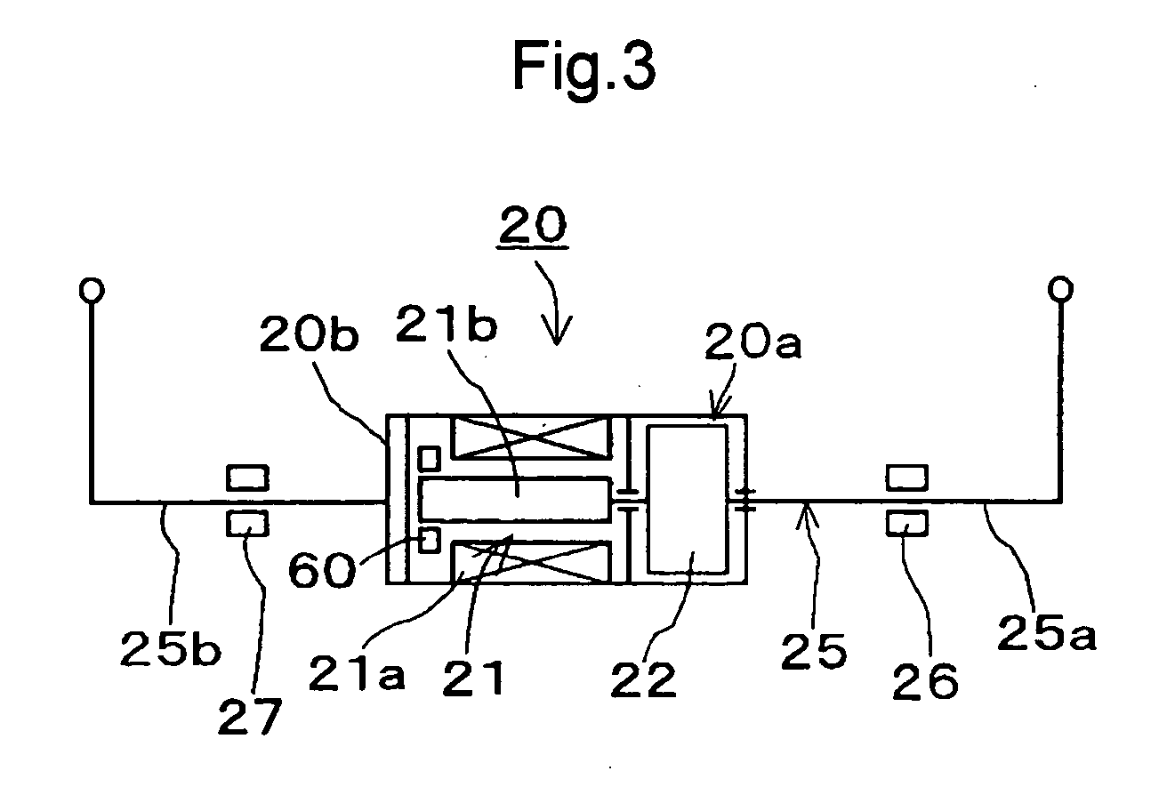
[0021] Hereinafter, embodiments of the present invention are explained, referring to the figures. FIG. 1 is a block diagram showing the electric configuration of a stabilizer control apparatus 10 according to an embodiment of the present invention. FIG. 2 is a figure that shows a vehicle 1 equipped with the stabilizer control apparatus 10. FIG. 3 is a figure that shows the configuration of a front stabilizer actuator 20 (hereinafter referred to as frontward actuator 20), with which the stabilizer control apparatus 10 is provided. FIGS. 4 to 7 are figures that illustrate operating states of the stabilizer control apparatus 10. The direction coming perpendicularly out of the paper plane in FIG. 2 is the travel direction of the vehicle 1. When referring to the rearward, frontward, left and right directions below, the travel direction of he vehicle 1 is regarded as the frontward direction.

[0022] As shown in FIGS. 1 and 2, the stabilizer control apparatus 10 includes for example a front...


PUM


Abstract

A stabilizer control apparatus operating to contort stabilizer bars ensures the stability of a vehicle, even in the event that one of the front and rear stabilizer bars of the vehicle is stuck in a contorted state. The stabilizer control apparatus includes frontward and rearward stabilizer bars 25 and 35, frontward and rearward stabilizer actuators 20, 30 that can be driven to contort the stabilizer bars 25 and 35 between their two ends, a lateral G sensor 42 or the like for detecting rolling of the vehicle and furthermore an ECU 50 that outputs to the stabilizer actuators 20 and 30 a driving signal to cause a resisting rolling moment countering rolling of the vehicle and that moreover, in the event that the irregularity is detected that one of the frontward and rearward stabilizer bars 25 and 35 is stuck in a contorted state, outputs to the stabilizer actuators 20 and 30 a driving signal to contort the other one of the frontward and rearward stabilizer bars 25 and 35 in the direction compensating that rolling moment.

Description

TECHNICAL FIELD [0001] The present invention relates to a stabilizer control apparatus for achieving stabilization of rolling in a running vehicle. BACKGROUND ART [0002] Conventionally, this type of stabilizer control apparatuses is known from after-mentioned Patent Document 1. In this conventional stabilizer control apparatus, a turning actuator is arranged between the two halves of a divided stabilizer bar. Then, in the event that the vehicle rolls, for example while the vehicle is rolling or the like, the turning actuator applies a contorting pre-stress between the stabilizer halves and applies a resisting moment to the vehicle. As a result, it is possible to stabilize the vehicle with respect to rolling moments. [0003] However, in this conventional stabilizer control apparatus, there is the risk that the vehicle front stays always tilted in the left or the right direction when the turning actuator is stuck while the stabilizer disposed at the front wheels of the vehicle is conto...

Claims


Application Information

Patent Timeline
Patent Type & Authority Applications(United States)
IPC IPC(8): B60G21/055B60G17/005B60G17/015B60G17/016
CPCB60G17/0162B60G21/0555B60G2800/0122B60G2202/42B60G2800/012B60G21/0558B60G17/015B60G21/05B60G21/055
Inventor SUZUKI, KATSUMITANEDA, AKIYA
Owner AISIN SEIKI KK
Why Eureka
Try Eureka