Vehicle brake hydraulic pressure control apparatus

a hydraulic pressure control and brake technology, applied in the direction of instruments, computing, electric digital data processing, etc., can solve the problems of vehicle sliding laterally, variable stability of the vehicle, and insufficient braking force, so as to prioritize the effect of ensuring stability

Active Publication Date: 2015-07-28
AUTOLIV NISSIN BRAKE SYST JAPAN CO LTD
View PDF27 Cites 0 Cited by
  • Summary
  • Abstract
  • Description
  • Claims
  • Application Information

AI Technical Summary

Benefits of technology

[0007]The invention has been made under the above circumstances and provides a vehicle brake hydraulic pressure control apparatus that ensures the stability of the vehicle by balancing the steering angle and the difference between the brake hydraulic pressures of the right and left wheel brakes and that ensures a sufficient braking force.
[0046]With the configuration of (18), when the control differential pressure changes from the low differential pressure region to the high differential pressure region, the upper limit value is changed so as to decrease gradually. Thereby, it is possible to smoothly switch between ensuring the braking performance in the low differential pressure region and ensuring the stability in the high differential pressure region.

Problems solved by technology

However, there may be a case where the vehicle is slid laterally due to unbalance between (i) a steering angle by driver's steering operation and (ii) a difference between the brake hydraulic pressures of the right and left wheel brakes.
However, if the differential pressure becomes small due to failure of those sensors, there is a possibility that the braking force may not be enough.
However, if the differential pressure becomes too large due to failure of those sensors, there is a possibility that the stability of the vehicle may be varied.

Method used


Image

  • Vehicle brake hydraulic pressure control apparatus
  • Vehicle brake hydraulic pressure control apparatus
  • Vehicle brake hydraulic pressure control apparatus

Examples


Embodiment Construction

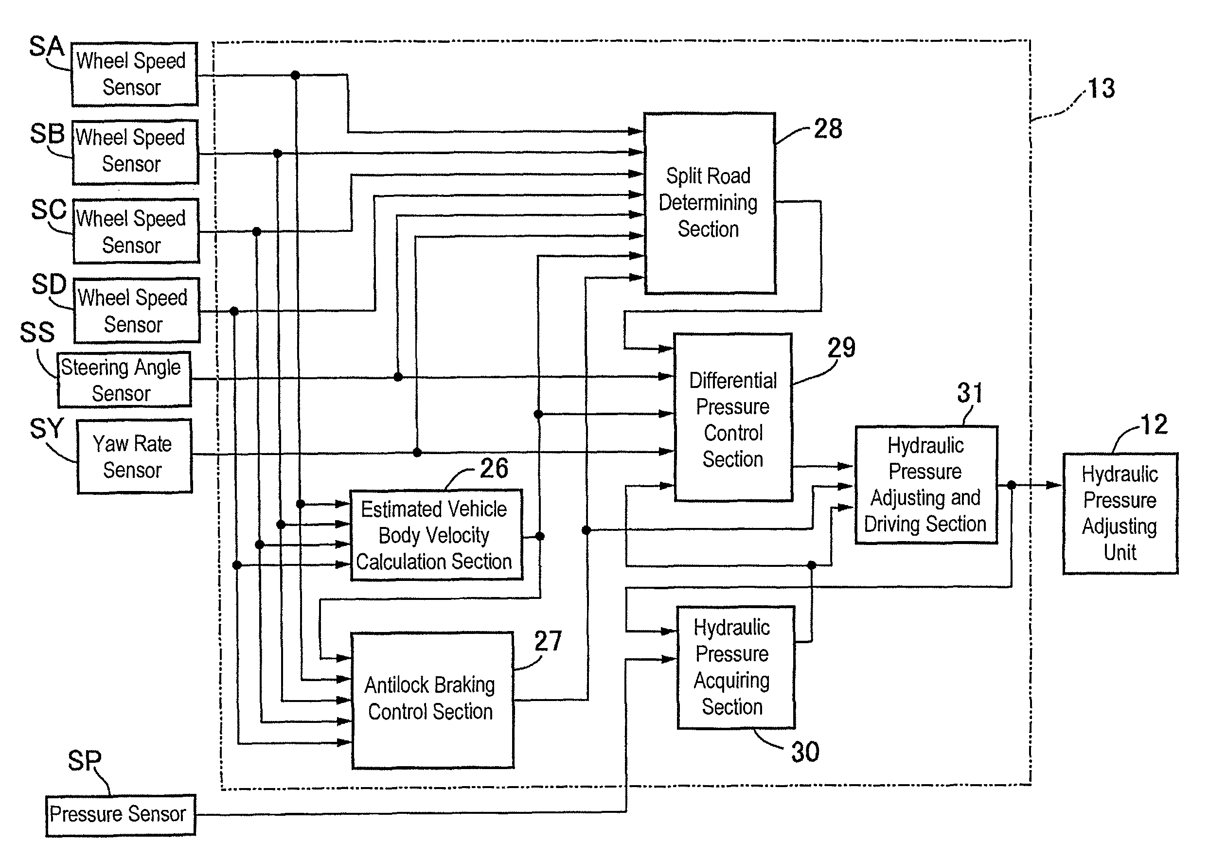
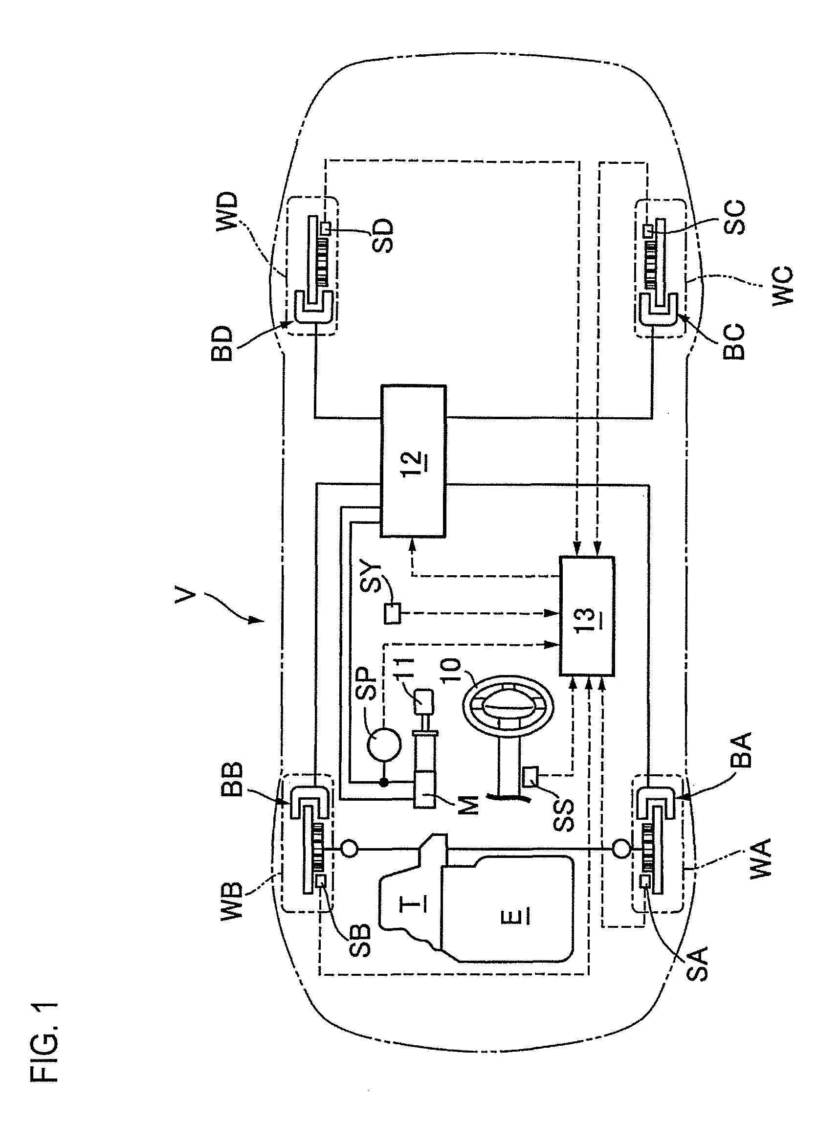
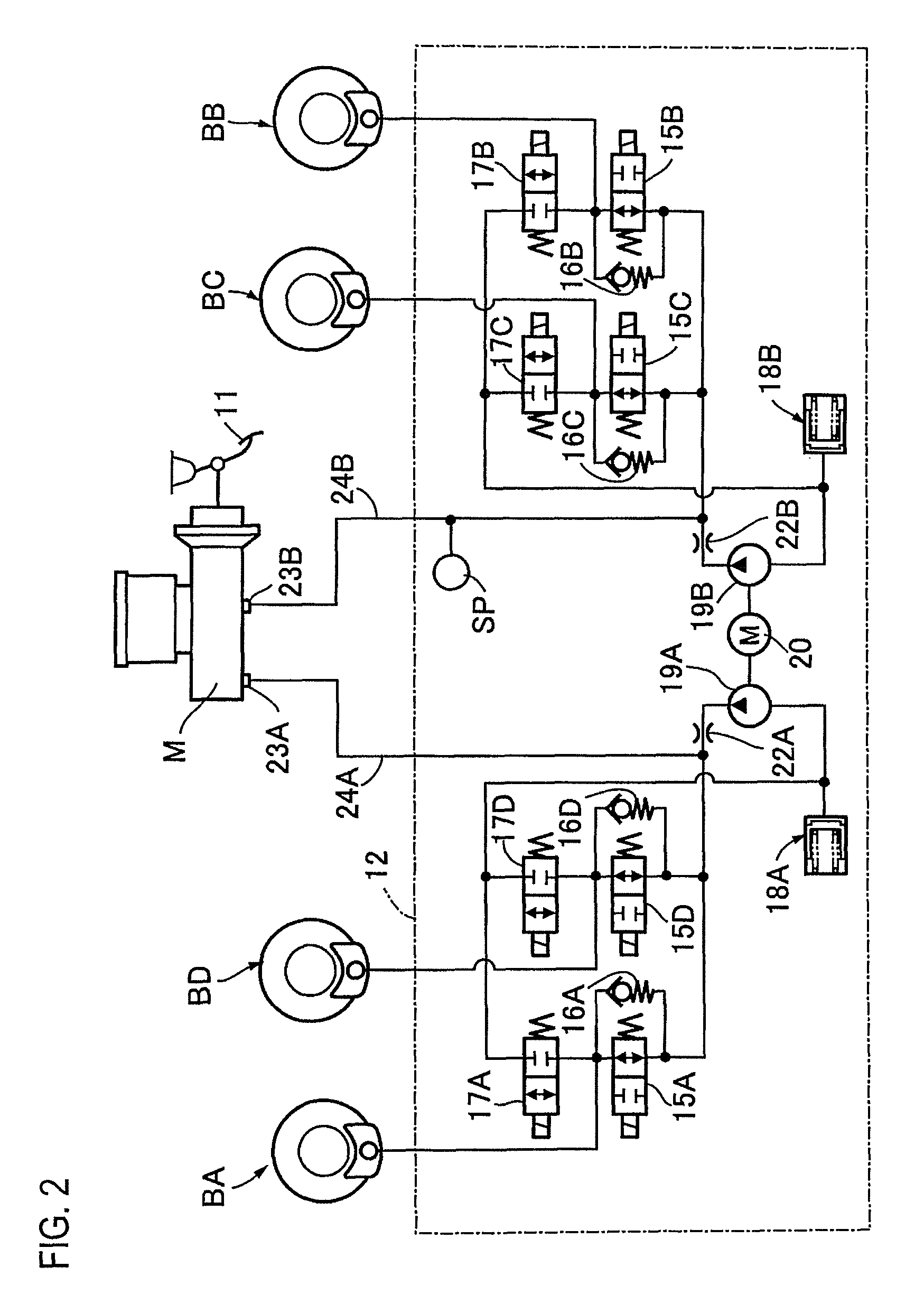
[0073]Embodiments of the invention will be described with reference to FIGS. 1 to 24C. In FIG. 1, a vehicle V includes left and right front wheels WA, WB to which a driving force of an engine E is transmitted via a transmission T and left and right rear wheels WC, WD. A brake pedal 11 that is controlled by a driver is connected to a master cylinder M. Also, wheel brakes BA, BB, BC, BD, which operate by means of a brake fluid pressure, are provided on the front wheels WA, WB and the rear wheels WC, WD, respectively. The master cylinder M is connected to the respective wheel brakes BA to BD via a hydraulic pressure adjusting unit 12. This hydraulic pressure adjusting unit 12 can adjust (increase or decrease) individually brake fluid pressures that act on the wheel brakes BA to BD in order to prevent wheels from being locked when the brakes are applied.

[0074]The operation of the hydraulic pressure adjusting unit 12 is controlled by a hydraulic pressure control device 13. Signals from w...


PUM


Abstract

A vehicle brake hydraulic pressure control apparatus includes an adding section and a control differential pressure setting section. The adding section adds a feedback differential pressure obtained by executing a PI operation in accordance with a yaw rate deviation which is a difference between a target yaw rate being set to a value at which a vehicle turns to a higher coefficient-of-friction road side and an actual yaw rate and a feedforward differential pressure obtained by adding (i) a differential pressure based on a steering angle and (ii) a differential pressure based on a velocity of a vehicle body and the target yaw rate. The control differential pressure setting section sets a control differential pressure based on a value obtained by the adding section, after a predetermined time elapses since start of differential pressure control.

Description

CROSS REFERENCE TO RELATED APPLICATION[0001]This application is based on and claims priority under 35 U.S.C. §119 to Japanese Patent Application Nos. 2012-59348, 2012-59349, and 2012-59350 (all of which were filed on Mar. 15, 2012), the entire contents of which are incorporated herein by reference.BACKGROUND[0002]1. Technical Field[0003]The invention relates to a vehicle brake hydraulic pressure control apparatus.[0004]2. Description of the Related Art[0005]JP 2007-55583 A (corresponding to US 2007 / 0029875 A1) describes a vehicle brake hydraulic pressure control apparatus that executes the antilock braking control for wheel brakes for right and left front wheels and right and left rear wheels independently from each other. In this vehicle brake hydraulic pressure control apparatus, when a vehicle is running during the antilock braking control on a split road in which coefficients of friction of right and left road surfaces with which the front and rear wheels are in contact are grea...

Claims


Application Information

Patent Timeline
Patent Type & Authority Patents(United States)
IPC IPC(8): B60T8/1764B60T8/1755
CPCB60T8/1764B60T8/17551
Inventor HIROSE, TOMONORIWAKIZAKA, KEISUKE
Owner AUTOLIV NISSIN BRAKE SYST JAPAN CO LTD
Why Eureka
Try Eureka