Vehicle brake control device

a technology of brake control and high- side wheel, which is applied in the direction of brake system, vehicle components, transportation and packaging, etc., can solve the problem of tensile behavior and achieve the effect of ensuring the stability of vehicle behavior and increasing the braking force of high- side wheel

Active Publication Date: 2017-09-05
ADVICS CO LTD
View PDF23 Cites 0 Cited by
  • Summary
  • Abstract
  • Description
  • Claims
  • Application Information

AI Technical Summary

Benefits of technology

[0007]In recent years, when such anti-lock brake control is applied to a vehicle travelling on a μ-split road surface, the deceleration of the vehicle is desired to be increased while ensuring the stability of the vehicle behavior.
[0008]It is an objective of the present invention to provide a vehicle brake control device that is capable of, when performing select-low anti-lock brake control in a vehicle that is travelling on a μ-split road surface, increasing the deceleration of the vehicle while ensuring the stability of the vehicle behavior.Means for Solving the Problems
[0011]During such select-low anti-lock brake control, the braking force on the high-μ side wheel, which is the second wheel, is greater when the tendency for instability in the vehicle behavior is small than when such tendency is large. Thus, under the condition that the vehicle behavior is stable, the overall braking force applied to the vehicle tends to be greater. Accordingly, when the select-low anti-lock brake control is executed in a vehicle travelling on a μ-split road surface, the deceleration of the vehicle can be increased while ensuring the stability of the vehicle behavior.
[0012]In the decrease period that is determined by the slip amount of the low-μ side wheel, which is the first wheel, there may be a case where the high-μ side wheel does not show the tendency to lock. In this case, the overall braking force applied to the vehicle can be increased by minimizing the decrease amount of the braking force on the high-μ side wheel in the decrease period. Thus, it is preferable that a decrease amount of the braking force on the second wheel in the decrease period be set to be smaller when the tendency for instability in the vehicle behavior is small than when such tendency is large. In such a structure, when the select-low anti-lock brake control is being executed in a vehicle travelling on a μ-split road surface, the braking force on the high-μ side wheel, which is the second wheel, does not easily decrease under the condition that the vehicle behavior is stable. This increases the overall braking force applied to the vehicle. Thus, the deceleration of the vehicle can be increased while ensuring the stability of the vehicle behavior.
[0014]In the above described vehicle brake control device, it is preferable that an increase amount of the braking force on the second wheel in the increase period be set to be greater when the tendency for instability in the vehicle behavior is small than when such tendency is large. In such a structure, when the select-low anti-lock brake control is being executed in a vehicle travelling on a μ-split road surface, the braking force on the high-μ side wheel, which is the second wheel, tends to increase under the condition that the vehicle behavior is stable. This allows the overall braking force applied to the vehicle to be increased. Thus, the deceleration of the vehicle can be increased while ensuring the stability of the vehicle behavior.
[0016]In the above described vehicle brake control device, the tendency for instability in the vehicle behavior may be determined such that the smaller a difference between a target yaw rate, which is set according to a condition of vehicle operation, and a yaw rate of the vehicle, the smaller the tendency for instability in the vehicle behavior becomes. In this configuration, when the vehicle yaw moment created by the execution of the soloct-low anti-lock brake control is small, the vehicle behavior is determined to be stable, and thus the braking force on the high-μ side wheel is easily increased. Accordingly, the deceleration of the vehicle can be increased while ensuring the stability of the vehicle behavior.

Problems solved by technology

Further, in this brake control device, the tendency of the high-μ side wheel to lock is observed.

Method used


Image

  • Vehicle brake control device
  • Vehicle brake control device
  • Vehicle brake control device

Examples


Embodiment Construction

[0025]A vehicle brake control device according to one embodiment will now be described with reference to the drawings.

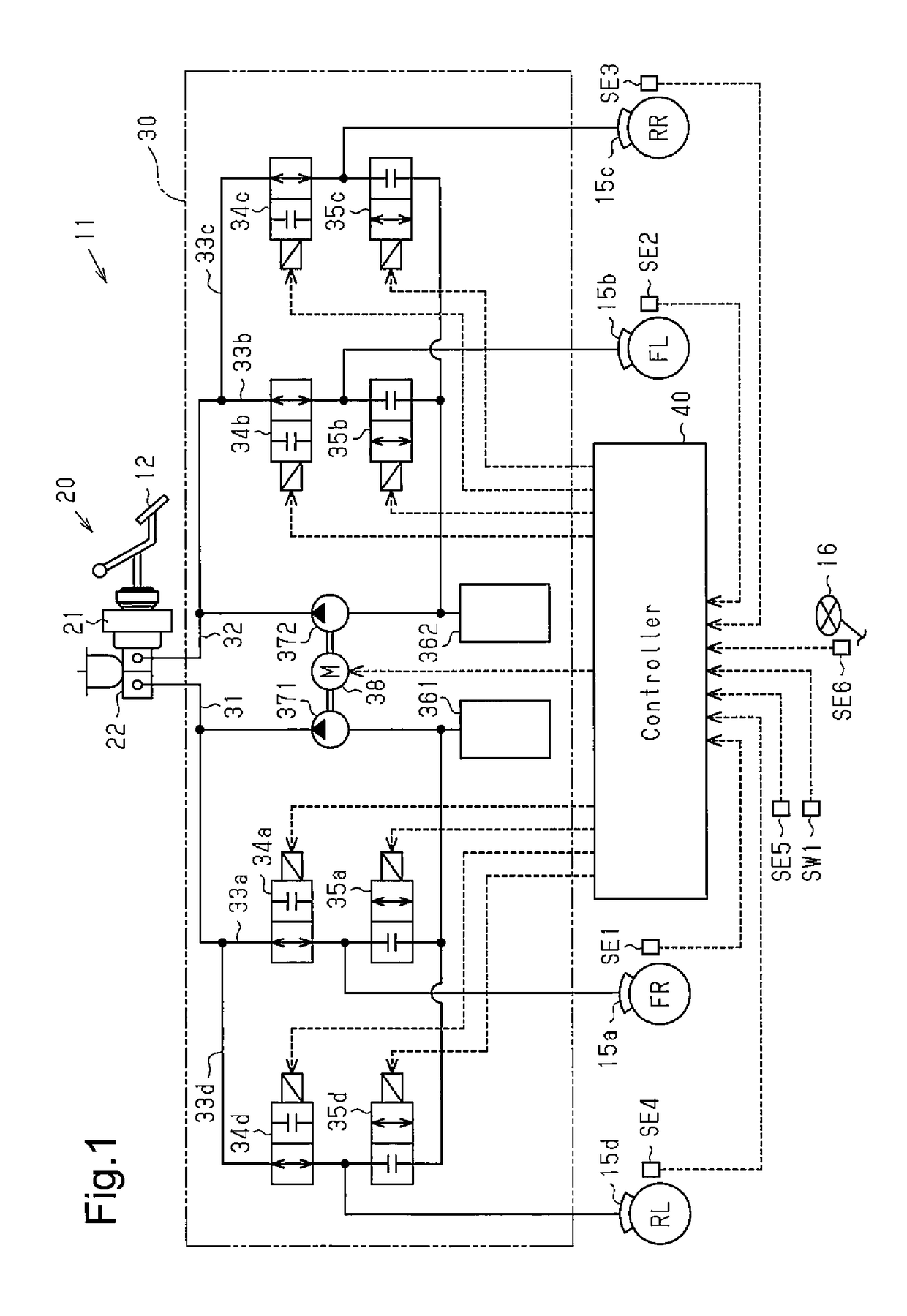
[0026]As shown in FIG. 1, a braking device 11 is installed in a vehicle that has a plurality of (four in the present embodiment) wheels (a front right wheel FR, a front left wheel FL, a rear right wheel RR, and a rear left wheel RL). The braking device 11 includes a fluid-pressure generating device 20, to which a brake pedal 12 is coupled, a brake actuator 30, which adjusts braking force on the wheels FR, FL, RR and RL, and a controller 40, which is an example of a brake control device and controls the brake actuator 30.

[0027]The fluid-pressure generating device 20 includes a booster 21, which boosts the braking force applied by the driver on the brake pedal 12, and a master cylinder 22, which generates brake fluid pressure (hereinafter also referred to as MC pressure) in accordance with the braking force boosted by the booster 21. When the driver is applying brakes,...


PUM


Abstract

A vehicle brake control device performs select-low anti-lock brake control. In the select-low anti-lock brake control, in a decrease period, in which braking force on a first wheel that is one of left and right wheels that has a lower wheel speed is decreased, braking force on a second wheel that is one of the left and right wheels that has a higher wheel speed is also decreased. In an increase period, in which the braking force on the first wheel is increased, the braking force on the second wheel is also increased. The vehicle brake control device is configured such that, when performing the anti-lock brake control, the vehicle brake device sets the braking force on the second wheel to be greater when the tendency for instability in the vehicle behavior is small than when such tendency is large.

Description

TECHNICAL FIELD[0001]The present invention relates to a vehicle brake control device for performing anti-lock brake control that limits wheel lock to ensure the steering performance of the vehicle.BACKGROUND ART[0002]Select-low anti-lock brake control is a known anti-lock brake control. This control identifies one of right and left wheels that has a lower wheel speed and determines a control cycle that includes a decrease period, in which braking force on the right and left wheels is decreased, and an increase period, in which the braking force is increased, based on the slip amount (or slip rate) of the identified wheel.[0003]Patent Document 1 discloses an example of a brake control device that performs select-low anti-lock brake control. When the driver applies the brakes, the controller determines based on the slip amounts of the right and left wheels whether the road surface on which the vehicle is traveling is a μ-split road surface, which refers to a road surface where the μ v...

Claims


Application Information

Patent Timeline
Patent Type & Authority Patents(United States)
IPC IPC(8): B60B39/00B60T8/1764B60T8/1755
CPCB60T8/1764B60T8/17551
Inventor TERASAKA, MASATOTSUKAMOTO, SHINJI
Owner ADVICS CO LTD
Why Eureka
Try Eureka