Brake control device for vehicles

a technology for brake control devices and vehicles, which is applied in the direction of brake systems, braking components, transportation and packaging, etc., can solve the problems of contradictory performance requirements of front-wheel and rear-wheel braking devices, and achieve the effects of reducing the size and weight of the brake control device, ensuring the stability of the vehicle, and high heat capacity

Active Publication Date: 2020-09-08
ADVICS CO LTD
View PDF4 Cites 0 Cited by
  • Summary
  • Abstract
  • Description
  • Claims
  • Application Information

AI Technical Summary

Benefits of technology

[0012]In a relatively mild braking operation over the long period of time (the long-term low-load braking state), relatively high heat capacity is requested for a rear-wheel braking device. In the brake control device according to the present invention, the rear-wheel braking force Fbr* is decreased, and the braking force Fbf* that is generated by a front-wheel braking device having room for the heat capacity is increased. Accordingly, in any of various braking operations, the heat capacity of each of the front-wheel and rear-wheel braking devices is appropriately regulated by braking force distribution control. Thus, reductions in size and weight of the brake control device as a whole can be achieved.
[0013]In addition, in the short-term high-load braking state, the predetermined front-rear braking force distribution ratio (the initial ratio) hbo is always adopted. Thus, stability of the vehicle is secured. The long-term low-load braking state is likely to occur in a situation where the vehicle slowly travels on the downhill road from a location at high altitudes. In this situation, center of gravity of the vehicle is slightly shifted to the front wheel side. Accordingly, the ratio Hbn of the rear-wheel braking force to the total braking force of the vehicle is corrected to be decreased. Thus, the rear-wheel braking force Fbr* is decreased while the front-wheel braking force Fbf* is increased. Therefore, braking force distribution that corresponds to a dynamic fluctuation of a wheel load caused by a slope road gradient can be achieved.
[0014]Furthermore, on a winding road (particularly, at a hairpin curve) on a downhill gradient, the stability of the vehicle is requested. In such a travel state, the rear-wheel distribution ratio Hbn is corrected to be decreased. Thus, a rear-wheel lateral force is secured. As a result, the stability of the vehicle can be improved.

Problems solved by technology

That is, of the various braking operation situations, there is a situation where requested performance for the front-wheel and rear-wheel braking devices contradict each other.
However, any of such changes is not preferred from a perspective of reductions in size and weight of the device.

Method used


Image

  • Brake control device for vehicles
  • Brake control device for vehicles
  • Brake control device for vehicles

Examples


Embodiment Construction

Reference Signs of Components and the Like and Additional Characters at End of Reference Signs

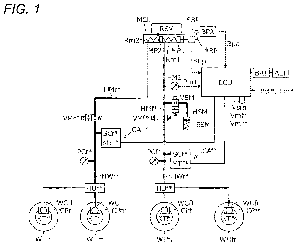
[0021]A description will be made on an embodiment of a brake control device for a vehicle according to the present invention with reference to the drawings. In the following description, like an “ECU”, components, calculation processing, signals, and values denoted by the same reference signs will have the same function. In addition, additional characters (“fr” and the like) provided at the end of various reference signs are generic signs, each of which indicates a relation to a wheel. More specifically, “fr”, “fl”, “rr”, and “rl” respectively indicate a right front wheel, a left front wheel, a right rear wheel, and a left rear wheel. For example, wheel cylinders will be described as a right-front wheel cylinder WCfr, a left-front wheel cylinder WCfl, a right-rear wheel cylinder WCrr, and a left-rear wheel cylinder WCrl.

[0022]The additional characters (“f*” and “r*”) provided at the end of ...


PUM


Abstract

This brake control device includes: an operation amount sensor which detects the brake operating member operation amount; front-wheel and rear-wheel actuators which generate braking force in front / rear wheels; front-wheel and rear-wheel sensors which detect the outputs of the front-wheel and rear-wheel actuators; and a controller which controls the front-wheel and rear-wheel actuators based on the operation amount and the outputs of the front and rear wheels. On the basis of the operation amount and / or the output of the rear wheels, the controller determines whether or not a long-term low-load state in which the friction member is continuously pressed against the rotary members of the rear wheels within a predetermined range over a long period of time is established. If so, the distribution ratio of the rear-wheel braking force to the total applied braking force is decreased compared to when a long-term low-load state is not determined to be established.

Description

TECHNICAL FIELD[0001]The present invention relates to a brake control device for a vehicle.BACKGROUND ART[0002]In Patent Literature 1, “braking force distribution control in which distribution of a braking force is changed in response to a request for braking performance under a high braking load without enlarging a braking device of a vehicle” is described. More specifically, it is described that “determination means for determining whether a high braking load state is established on the basis of intervals and the number of executions of braking execution processing and distribution control means for changing front and rear wheel braking force distribution of the vehicle when it is determined that the high braking load state is established are provided, the high braking load state is detected in the cases where the braking execution processing of requesting the braking force that exceeds a specified braking force and driving execution processing of requesting a driving force that e...

Claims


Application Information

Patent Timeline
Patent Type & Authority Patents(United States)
IPC IPC(8): B60T8/30
CPCB60T8/30B60T1/10B60T8/1766B60T13/586B60T13/588B60T13/662B60T2201/04B60T2210/30B60T2220/04B60T2270/604F16D61/00
Inventor YUKOKU, SHINICHIROHISHIKAWA, TAKAHISA
Owner ADVICS CO LTD
Why Eureka
Try Eureka