Identification badges with RFID tags and methods thereof

a technology of identification badges and rfid tags, applied in the field of radio frequency identification devices, can solve the problems of rfid readers not being able to communicate with a tag located very close to the body of a human, compromising the reliability of rfid reading,

Inactive Publication Date: 2006-11-09
LASER REGISTRATION LRI
View PDF11 Cites 20 Cited by
  • Summary
  • Abstract
  • Description
  • Claims
  • Application Information

AI Technical Summary

Benefits of technology

[0009] An identification badge in accordance with embodiments of the present invention includes a badge holder having at least one surface, an RFID tag affixed to the badge holder or the badge itself, and a spacer adapted to extend away from the at least one surface. The spacer creates a first distance between the RFID tag and a body of a person wearing the identification badge.
[0010] A method of making ...

Problems solved by technology

When the conditions are satisfactory, the tag can be successfully read or written, otherwise communication is not possible.
Unfortunately, one of the problems with RFID is that water absorbs UHF signals and can therefore compromise the reliability of the reading of RFID tags.
Since human beings are composed mostly of water (about 60%), RFID readers will not be able to communicate with a tag located very close to the body of a human.
For the reasons given above, simply affixing an RFID tag to the paper badge or badge holder will not yield acceptable results, much less tha...

Method used


Image

  • Identification badges with RFID tags and methods thereof
  • Identification badges with RFID tags and methods thereof
  • Identification badges with RFID tags and methods thereof

Examples


third embodiment

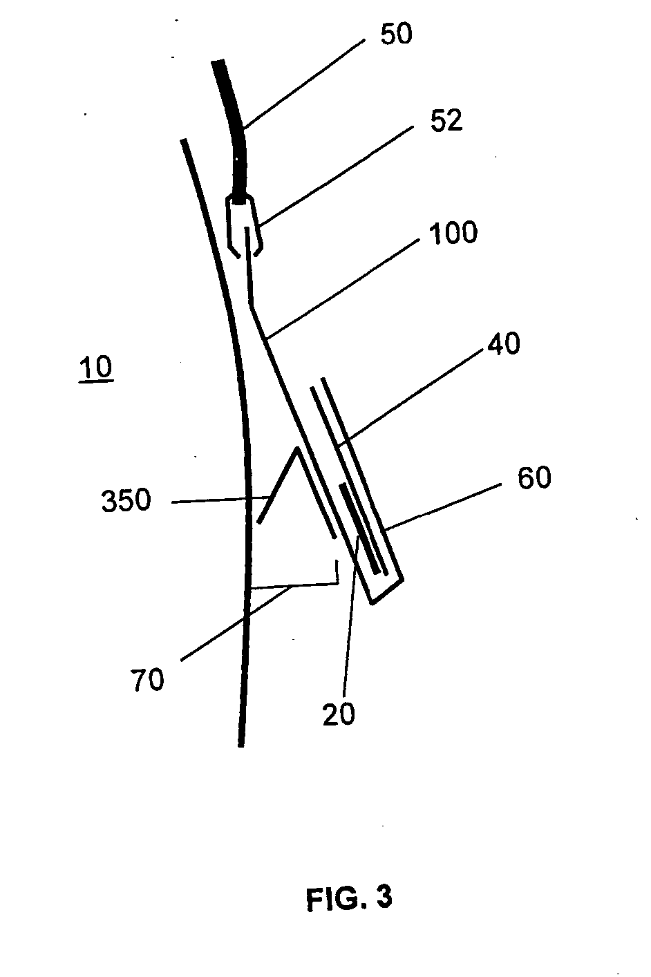
[0022] Referring to FIG. 3, there is shown another embodiment of the badge holder 100 of the present invention. In this third embodiment, the spacer 350 is a bent layer of material connected to and which extends out from the badge holder 100 to provide the desired distance 70. The material which composes the spacer 350 should preferably be resilient in order for the bent layer 350 to keep its shape and thus, the desired distance 70 between the RFID tag 20 and the body 10. It is understood that other types of shapes and configurations and numbers of layers and elements can be used for the spacer 350.

[0023] Referring to FIGS. 4 to 6, there is shown yet another embodiment of the badge holder 100 of the present invention. In this fourth embodiment, the badge holder 100 generally comprises at least two layers 410 and 415 of material. The front layer 410, partially shown in FIG. 6, is adapted to receive a badge 40, generally but not exclusively by means of a pocket (similar to pocket 60)....

fourth embodiment

[0024] The skilled addressee will understand that the fourth embodiment shall also generally be equipped with a lanyard 50 and clips 52 or other similar securing device.

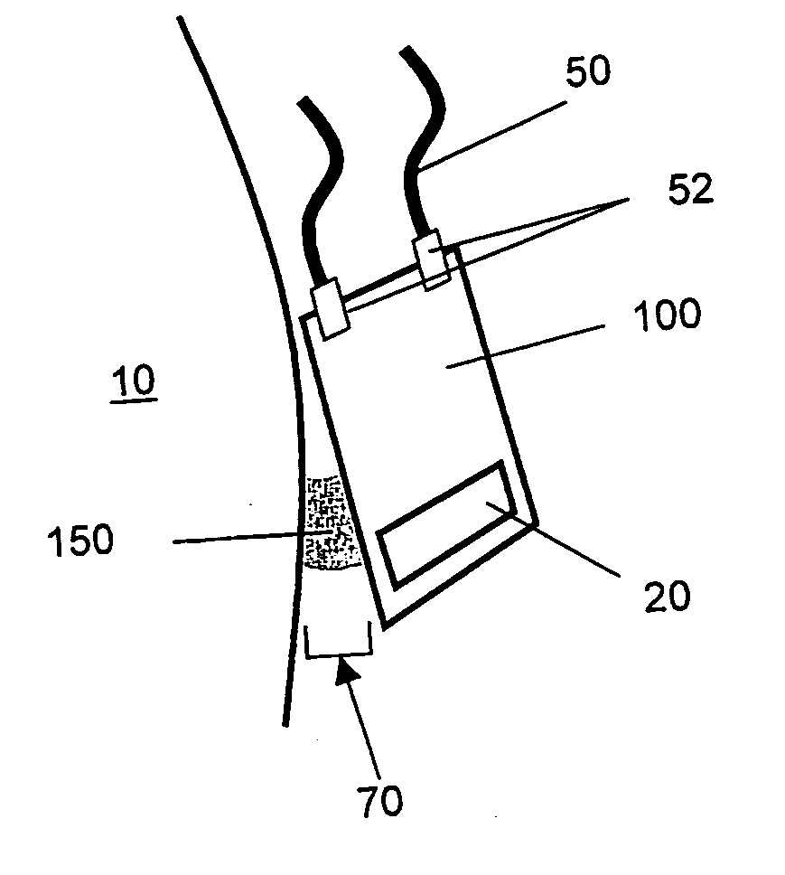
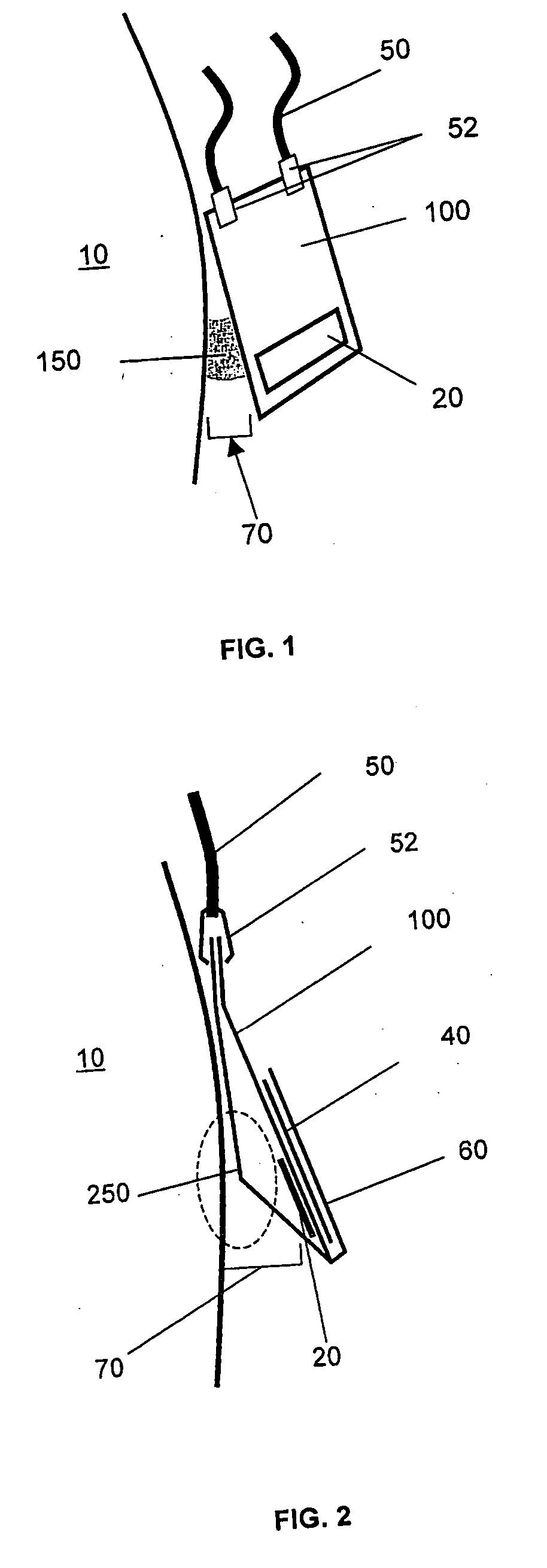
[0025] In all these embodiments, the RFID tag 20 can be either directly connected to the badge holder 100, or connected to the badge 40. In FIG. 2, the tag 20 is directly connected to the badge holder 100. Alternatively, in FIG. 3, the tag 20 is connected directly on the badge 40 which is located in the badge holder pocket 60. Whether it is attached to the badge holder 100 or the badge 40, the RFID tag 20 can be affixed in a variety of manners, such as with glue.

[0026] Additionally, the badge holders 100 can be produced in large quantities with the RFID tag 20 included, such as in FIG. 2. If the RFID tag 20 is attached to the name badge 40, the name badge 40 with the RFID tag 20 can be sent to the user by mail in a regular envelope or can be delivered in other manners.

[0027] The badge holder is secured around the n...


PUM


Abstract

An identification badge includes a badge holder having at least one surface, means to receive a name tag, an RFID tag affixed to the badge holder or the name tag, and a spacer adapted to extend away from the at least one surface. The spacer creates a first distance between the RFID tag and a body of a person wearing the identification badge.

Description

CROSS-REFERENCE TO RELATED APPLICATIONS [0001] This present application is based on commonly assigned U.S. patent provisional application Ser. No. 60 / 663,989, filed on Mar. 22, 2005 and entitled “Identification Badges with RFID Tags and Methods Thereof”.FIELD OF THE INVENTION [0002] The present invention generally relates radio frequency identification devices (“RFID”) devices and, more particularly, to identification badges with RFID tags and methods thereof. BACKGROUND OF THE INVENTION [0003] The purpose of an RFID system is to enable data to be transmitted between a tag (a chip embedded in a very small portable device) and an RFID reader via an antenna. Tags are most often passive, which means they are powered by the magnetic field emitted from the antenna. Therefore when a tag is put in proximity to an antenna, it is powered and the reader can read or write data on the tag. All readers have a range that depends on the surrounding conditions: respective positions and orientations...

Claims


Application Information

Patent Timeline
IPC IPC(8): G08B13/14
CPCG06K19/07771G06K19/07749
Inventor HARRIS, SIMONMELIS, TONYVANDAMME, PATRICK
Owner LASER REGISTRATION LRI
Why Eureka
Try Eureka