Tension clamp and fastening point for the fastening of a rail to the ground

Active Publication Date: 2022-11-08
VOSSLOH WERKE GMBH
View PDF33 Cites 0 Cited by
  • Summary
  • Abstract
  • Description
  • Claims
  • Application Information

AI Technical Summary

Problems solved by technology

Periodically, recurrent errors on the rails or on the edges of the rail vehicle can lead to resonance peaks.
This results in a premature and sudden failure of the tension clamp as a result of a break that typically occurs in the region of the torsional sections or in the transition area of the supporting arms in the direction of the torsional sections.
However, the test also showed that vibration absorbers of this type were highly effective but susceptible to destruction, so the article came to the conclusion that the practical usability of absorbers of this type is questionable.
The relative movements that are necessarily exerted by the te

Method used


Image

  • Tension clamp and fastening point for the fastening of a rail to the ground
  • Tension clamp and fastening point for the fastening of a rail to the ground
  • Tension clamp and fastening point for the fastening of a rail to the ground

Examples


Embodiment Construction

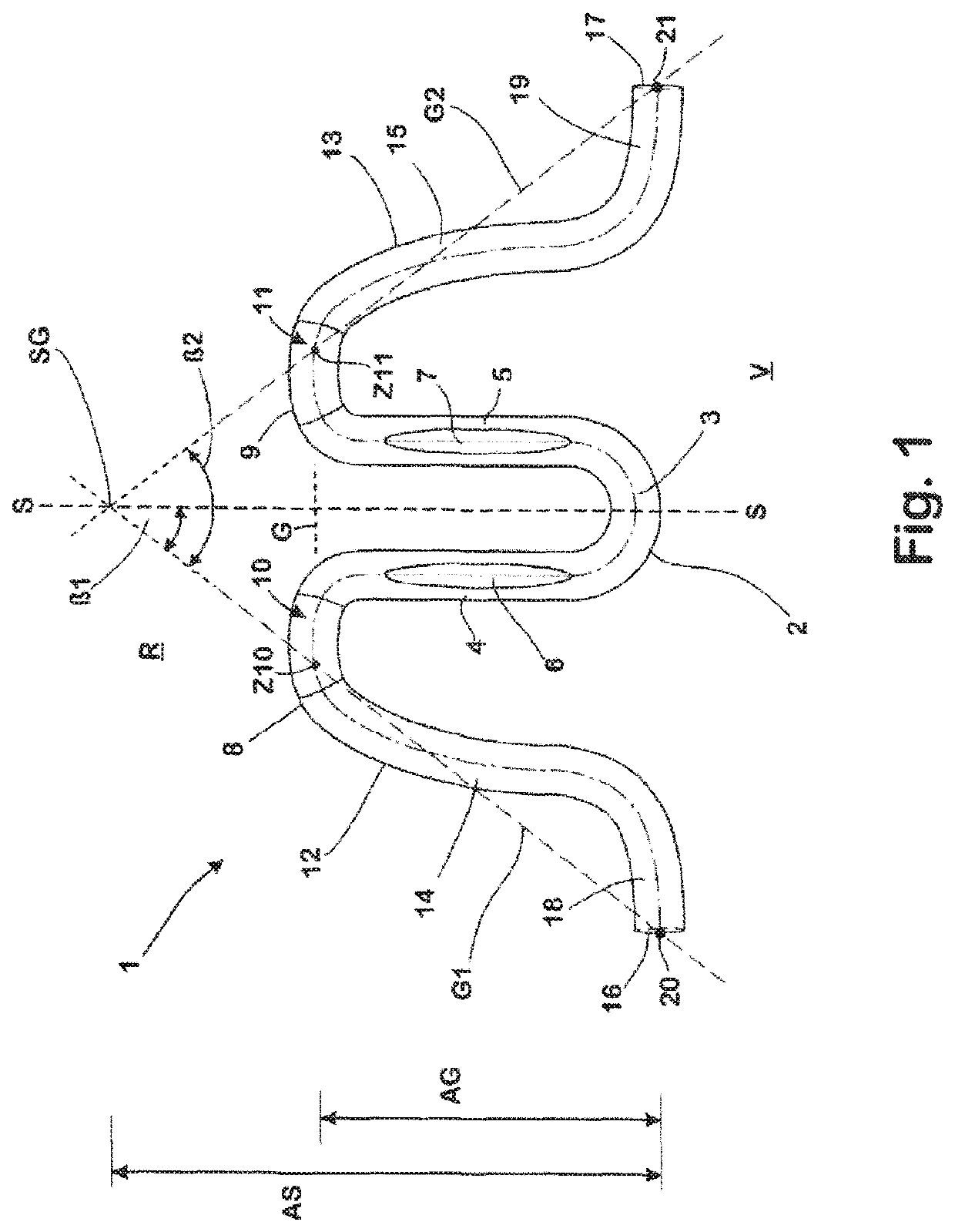
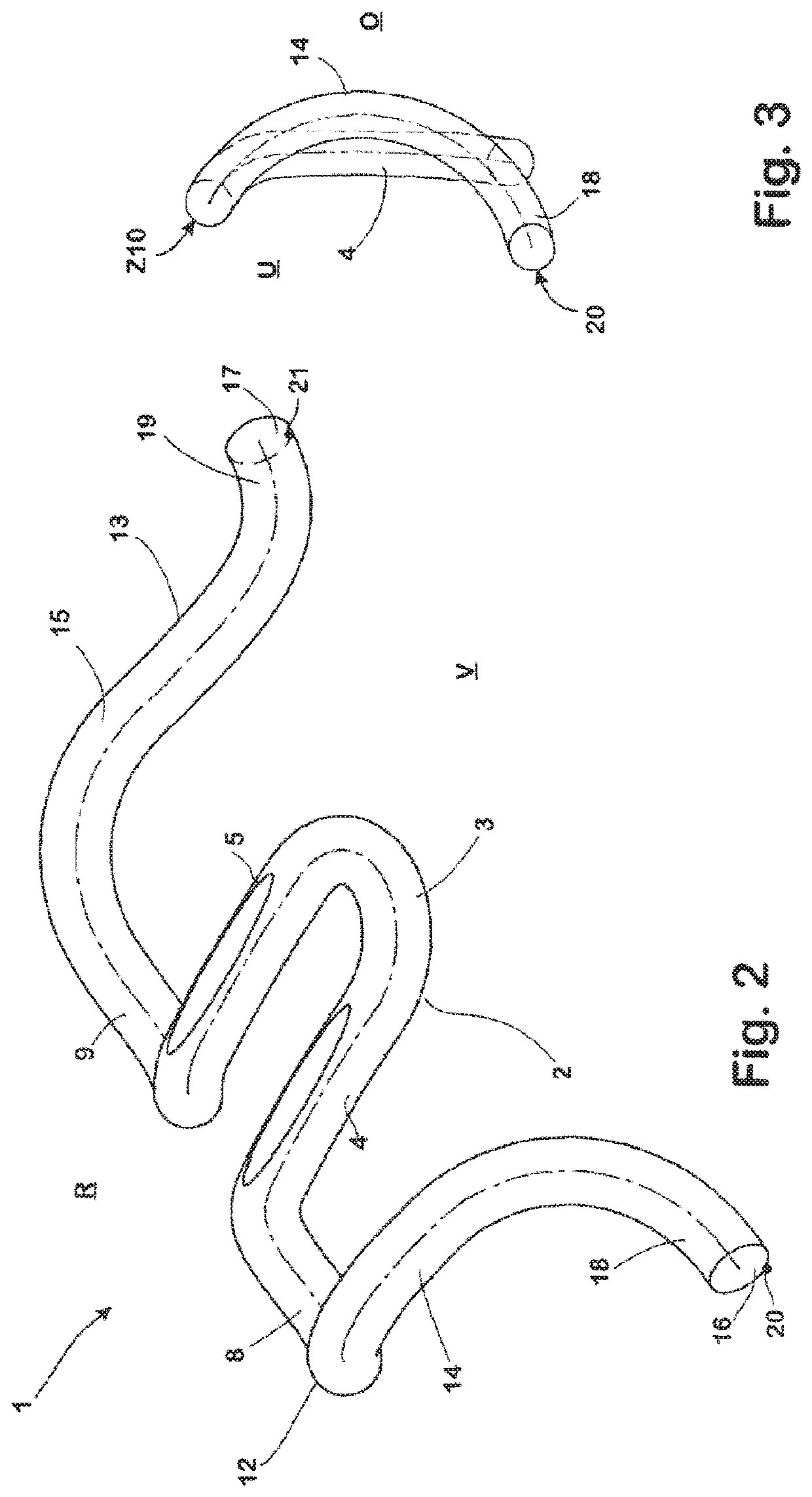
[0053]The tension clamp 1 according to the invention that is shown in FIGS. 1-3 and curved into a single piece from a spring wire with a circular cross section has a U-shaped central section 2 having a base section 3 allocated to the front face V of the tension clamp and straight legs 4, 5 connected to said base section. Flattened contact surfaces 6, 7 are provided on the upper face of the legs 4, 5 of the central section 2 allocated to the upper face O of the tension clamp 1, on which contact surfaces a sleeper screen sits with its screw head as a tensioning element to tension the tension clamp 1 during use (not shown).

[0054]The legs 4, 5 of the central section 2 each pass into a torsional section 8, 9 of the tension clamp 1 on the ends that point away from the base section 3 and towards the rear face R of the tension clamp 1. The torsional sections 8, 9 are curved in the direction of the lower face U of the tension clamp 1 and lead in a lateral direction outwards from the respecti...


PUM


Abstract

The invention relates to a tension clamp for the holding of a rail for rail vehicles and a rail fastening point. The tension clamp has a central section having two legs, two torsional sections connected thereto and leading away laterally in an outwards direction having a supporting zone, and two supporting arms connected to the torsional sections. The supporting arms run to the front face of the tension clamp and have a spring section and a support section with a supporting zone. The fact that the support sections point laterally in an outwards direction such that the straight lines which in each case connect the centers of the supporting zones and the torsional section allocated to the supporting arm in an area on the rear face of the tension element increases the natural frequencies of the tension clamp such that they are outside of stimulation frequencies that occur in practice.

Description

CROSS-REFERENCE TO RELATED APPLICATIONS[0001]This application is the United States national phase of International Application No. PCT / EP2017 / 078781 filed Nov. 9, 2017, and claims priority to German Patent Application Nos. 10 2016 122 062.0 filed Nov. 16, 2016, and 10 2017 111 781.4 filed May 30, 2017, the disclosures of which are hereby incorporated by reference in their entirety.BACKGROUND OF THE INVENTION[0002]The invention relates to a tension clamp for fastening a rail for rail vehicles.[0003]The invention further relates to a fastening point in which a rail for a rail vehicle is fastened to a ground.[0004]The ground on which a fastening point according to the invention is established is typically a sleeper or plate made of a solid material such as concrete or similar. The fastening point according to the invention can, however, also be mounted on conventional wooden sleepers serving as the ground.[0005]The rails fastened by means of the components and fastening points improved...

Claims


Application Information

Patent Timeline
IPC IPC(8): E01B9/30E01B9/48
CPCE01B9/303E01B9/483E01B2201/00E01B2201/08
Inventor BÖSTERLING, WINFRIEDLIU, DUO
Owner VOSSLOH WERKE GMBH
Why Eureka
Try Eureka