Foil for providing a peel-seal valve, package comprising the foil, and method of manufacturing the foil

a technology for peeling valves and foils, which is applied in the direction of closure lids, lamination, containers, etc., can solve the problems of affecting the usability of the package, so as to improve the usability and control. the effect of improving the control

Inactive Publication Date: 2012-08-16
MONDI GROUP
View PDF2 Cites 14 Cited by
  • Summary
  • Abstract
  • Description
  • Claims
  • Application Information

AI Technical Summary

Benefits of technology

[0042]According to a first aspect of the second embodiment the sealing of the punctures is realized by a solidly extension of the adhesive layer around an area of the punctures. In this embodiment only the area of the punctures is left free from adhesive, while apart from this area the two films are completely laminated onto each other. This solution is of particular interest if it is decided to have the area of the punctures grouped, e.g. in a circle, and located in close proximity to the outer edge of the foil. This allows limiting the distance necessary to create the tunnel in form of the crack in the first plastic film and therefore also limits the force necessary to create the crack to a desired value, which otherwise would hardly be possible to achieve.
[0043]According to a second aspect of the second embodiment the sealing of the punctures is realized in form of a number of stripe-like extensions of the adhesive layer located within a channel into which the punctures are entering, the channel extends between the two films and ends at the outer edge region of the foil. This solution also allows controlling the gas flow within the two plastic films in any desired direction. Also the force to be applied to create a crack is better controlled and can be better tuned when compared with the first aspect of the second embodiment.
[0044]With regard to the second embodiment it is to mention that the stripes may be located along the channel at any desired position while leaving out the position of the punctures. The direction of the stripes may also be alternated from stripe to stripe or group of stripes. Stripes may also overlap in order to cerate a web-like structure within the plane or more precisely along the channel and openings of the punctures may be located in-between the stripes. However, in a preferred embodiment the number of stripes is located adjacent to the outer edge region of the foil in an area of the channel that is free of punctures. This embodiment provides the advantage that the force necessary to cerate the cracks at the position of the stripes is lower and can be better controlled and the risk of applying adhesive at a position of a puncture is reduced or completely avoided. Hence, the punctures can be created at any arbitrary position along the channel provided that the outer region of the foil where the stripes are located is omitted. Hence, the stripes and punctures do not any more need to be created in register with each other.
[0045]Basically the channel may end only at one position at the outer edge of the foil. This is true not only for the second embodiment but also for the first embodiment. However, in the context of the second embodiment it has proved to be of particular advantage if the channel ends at the outer edge of the foil at two different positions. In particular, the channel may have a form of a straight line with parallel channel boundaries and openings of the punctures are distributed within said channel. When orienting the channel in direction of the manufacturing process the application of the adhesive and the creation of the punctures are widely decoupled, hence creation of the adhesive layer and the punctures is simplified.
[0046]Also the first embodiment is significantly improved in terms of manufacturing art if the adhesive layer leaves open a channel that has a form of a straight line with parallel channel boundaries and openings of the punctures that open into the channel, wherein said openings are aligned in a row in parallel to the channel boundaries and the channel ends at the first peel-able seal at two different positions. In the present case the generation of the puncture and the application of the adhesive layer on both sides of the channel can be performed out of register. This significantly reduces the accuracy requirements in the manufacturing process of the foil.

Problems solved by technology

However, it also shows some drawbacks.
For example, as soon as the temperature range used is extended towards extremely low temperatures, the solution may suffer in terms of reliability.
But also regulatory frameworks may hamper the usability of the package.
Typically the food or meal contained in the package is not allowed to come into contact with the material of the layer, which during normal use will not be the case at all.
However, improper handling of the package like placing it into a microwave oven up-side-down with the lid facing downward would certainly lead into a situation in which the food via its liquid components would probably come into contact with the melting hot melt glue or layer.
Such accidental food contact is heavily undesired.
But also during the manufacturing of the lid and its consecutive handling or transportation several drawbacks are introduced by the layer based solution.
This in fact creates a sort of a bump on the plane foil.
For both storage systems—roll or magazine—the existence of the bump creates difficulties and may led to malfunction during automated handling of the storage system.
A further back draw of the solution with melting layer is its sensitivity to heat, hence its use is limited to chilled and ambient temperatures.
Offline manufacturing of label alone also imposes high costs on the solution.
Further group of valve solutions use peel able lacquers applied in the sealing area in between the lid and the tray or between two layers of the lidding film in the tray sealing area whilst the food contact layer of the lidding film is cut also in the sealing area and represents a potential risk of leakage of the pack.

Method used


Image

  • Foil for providing a peel-seal valve, package comprising the foil, and method of manufacturing the foil
  • Foil for providing a peel-seal valve, package comprising the foil, and method of manufacturing the foil
  • Foil for providing a peel-seal valve, package comprising the foil, and method of manufacturing the foil

Examples


first embodiment

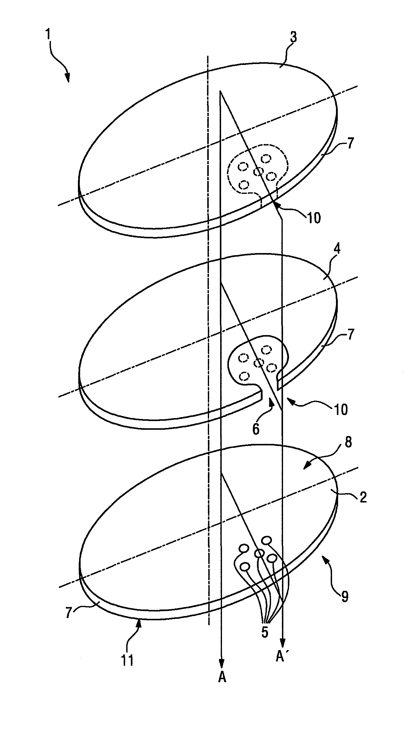
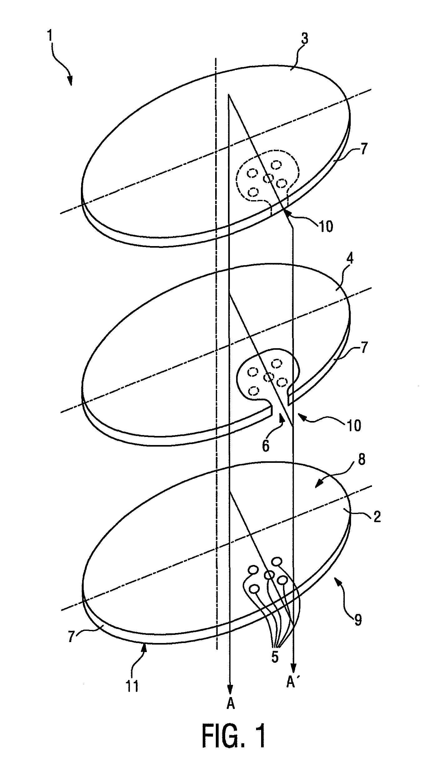
[0059]FIG. 1 shows three layers of a foil 1 according to the invention, wherein each layer is typically in contact with its neighboring layer(s) but for the sake of clarity in FIG. 1 shown with distance to each other. The three layers are a first plastic film 2, a second plastic film 3 and an adhesive layer 4 interposed between the first plastic film 2 and the second plastic film 3. The adhesive layer 4 laminates the two films 2 and 3 together.

[0060]The first plastic film 2 comprises a number of punctures 5, wherein in the present embodiment only five of these punctures 5 are shown because of clarity reasons. In reality the number of punctures 5 might be selected to be much higher and the diameter of the punctures 5 might be much smaller. In the two layers visualized above the first plastic film 2 broken lines indicate the position of the punctures 5 schematically. The adhesive layer 4 leaves open the punctures 5 such that gas can penetrate through the punctures 5 in-between the two...

third embodiment

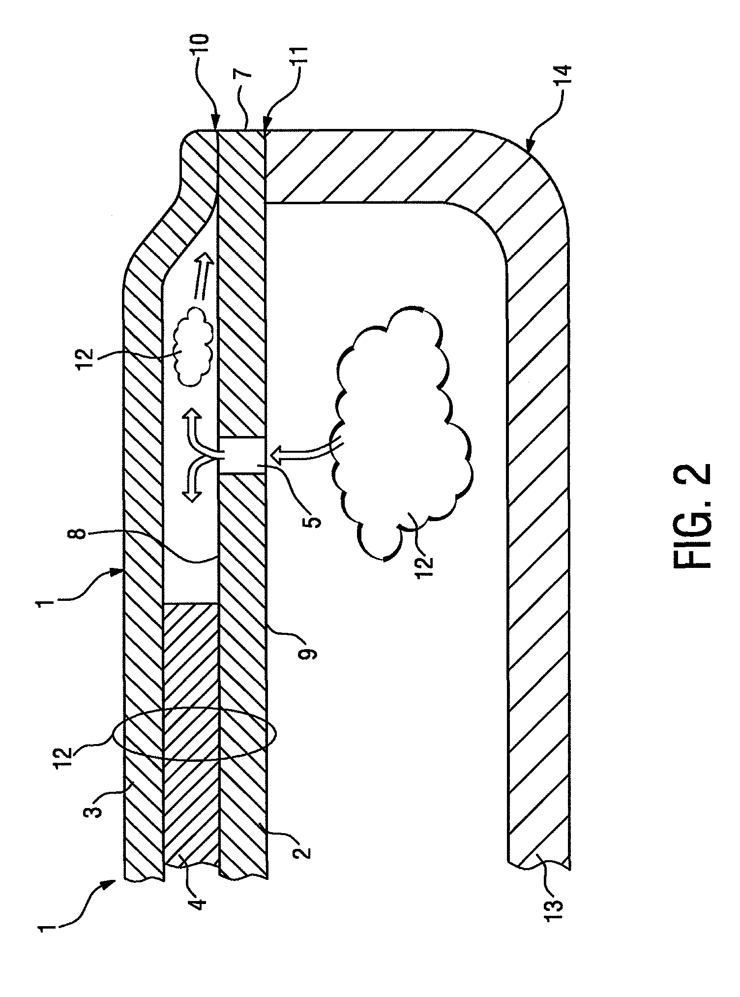
[0073]FIGS. 7 to 9 relates to the foil 2 according to the invention and its application in a package 14. According to this embodiment between the two films 2 and 3 the adhesive layer 2 tightly seals the punctures 5 from an outer edge 7 of the foil 2. Given the tight sealing by the aid of the adhesive layer 4, which implies that the two films 2 and 3 are spaced from each other and can not any more be sealed together, the first peel-able seal 10 is now created by another property of the first plastic film 2. In the present case the first plastic film 2 is designed to cerate in its structure a cohesive crack adjacent to the adhesive layer. This design allows to cerate a cohesion peel seal.

[0074]The structure of the foil 2 is visualized in FIG. 7, in which context it is emphasized that the sealing of the punctures 5 is realized in form of a number of strip-like extensions 17 of the adhesive layer 4 located within the channel 6 into which the punctures 5 are entering. The channel 6 exten...


PUM

PropertyMeasurementUnit
temperaturesaaaaaaaaaa
thicknessaaaaaaaaaa
thicknessaaaaaaaaaa

Abstract

A foil made of two plastic films and an adhesive layer laminating the two films together, wherein the first plastic film has a first side and a second side and comprises punctures therebetween. The foil is of a dual peel-seal type such that the first plastic film realizes a first peel-able seal within the foil at its first side in the form of an adhesion peel seal in an open state and/or in the form of a cohesion peel seal in a sealed state, and wherein the adhesive layer leaves open the punctures such that gas can penetrate through the punctures in-between the two films towards the first peel-able seal.

Description

FIELD OF THE INVENTION[0001]The invention relates to a foil of the peel-seal type that realizes a valve of a food package.[0002]The invention also relates to a package for food comprising a tray and a lid made from a foil according to the first paragraph.[0003]The invention also relates to a flexible package made from a foil according to the first paragraph.[0004]The invention further relates to a method of manufacturing a foil of the peel-seal type that realizes a valve of a food package.BACKGROUND OF THE INVENTION[0005]Today food products are often pre-prepared and sold as so-termed convenient meals. For consumer convenience such meals are packed in packages allowing for the heating or cooking of the meal contained therein without removal of the packaging. When heated up, e.g. in a microwave oven, typically moisture contained in the food converts into steam. In order to cope with the rise of the internal gas-pressure such a package comprises a valve, which allows the steam to esca...

Claims


Application Information

Patent Timeline
Patent Type & Authority Applications(United States)
IPC IPC(8): B65D51/16B65D51/00B29C65/76
CPCB65D77/225B65D81/3453B65D2205/00B65D81/3446B65D51/1638B65D77/206B65D51/1633
Inventor MADAI, GYULAVOLLMER, JAN-TORSTENBUDAI, MELINDASEEBER, MICHAELMUMELTER, BERNHARD
Owner MONDI GROUP
Why Eureka
Try Eureka