
Tunnel provisioning with link aggregation

a tunneling and link technology, applied in the field of communication networks, can solve the problems of poor service quality and the inability of the link aggregation process to guarantee bandwidth

Active Publication Date: 2006-11-09
CORRIGENT CORP
View PDF82 Cites 107 Cited by
  • Summary
  • Abstract
  • Description
  • Claims
  • Application Information

AI Technical Summary

Benefits of technology

[0011] The link aggregation process does not guarantee bandwidth in the event that one or more Ethernet ports fail or are taken out of service. It is desirable to guarantee the allocated bandwidth of an MPLS tunnel during port failure or reconfiguration.

Problems solved by technology

This lack of coordination may cause several problems.
This contradiction may result in poor service quality, since multiple flows may be directed to the same Ethernet port, which may be unable to deliver the bandwidth allocated by the RSVP-TE admission control module.
The link aggregation process does not guarantee bandwidth in the event that one or more Ethernet ports fail or are taken out of service.

Method used


Image

  • Tunnel provisioning with link aggregation
  • Tunnel provisioning with link aggregation
  • Tunnel provisioning with link aggregation

Examples


Embodiment Construction

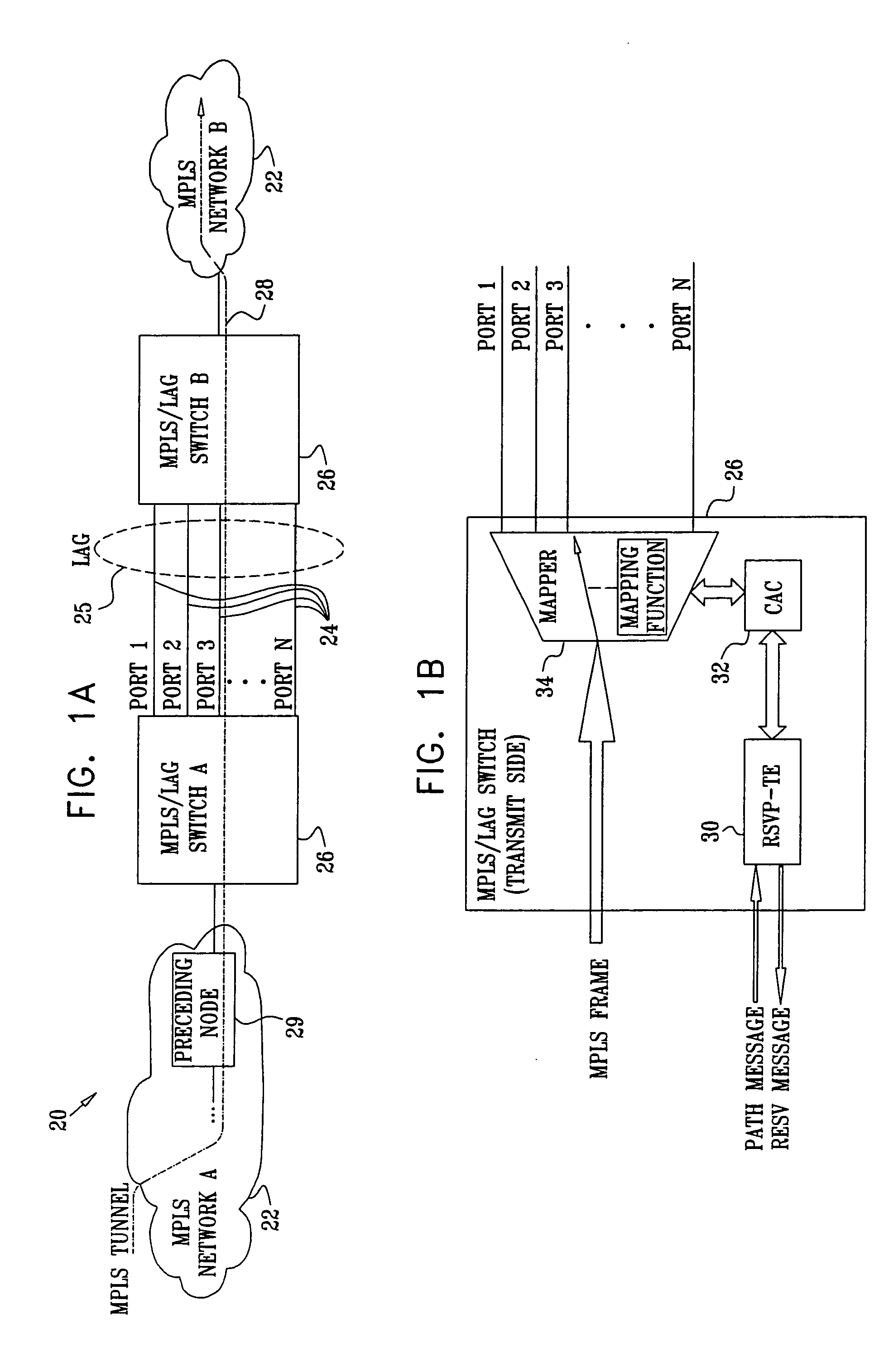
[0038]FIG. 1A is a block diagram that schematically illustrates a computer communication network 20, in accordance with an embodiment of the present invention. System 20 comprises two MPLS networks 22, labeled A and B, i.e., networks containing MPLS-capable switches. (Typically, these networks may also carry non-MPLS traffic, as in MPLS-capable IP networks that are known in the art.) MPLS networks A and B are connected via MPLS / LAG switches 26, using N physical Ethernet ports 24. Ports 24 are aggregated into a LAG group 25 using link aggregation (LAG) methods defined in the IEEE 802.3ad specification cited above. The two MPLS / LAG switches 26, which also function as LSRs, perform link aggregation and other packet routing / switching functions, according to methods which will be described below.

[0039] An MPLS tunnel 28 (a label switched path, or LSP, according to the MPLS specification cited above) is established from an ingress node in MPLS network A, through the two switches and the ...


PUM


Abstract

A method for processing data packets in a communication network includes establishing a path for a flow of the data packets through the communication network. At a node along the path having a plurality of aggregated ports, a port is selected from among the plurality to serve as part of the path. A label is chosen responsively to the selected port. The label is attached to the data packets in the flow at a point on the path upstream from the node. Upon receiving the data packets at the node, the data packets are switched through the selected port responsively to the label.

Description

FIELD OF THE INVENTION [0001] The present invention relates generally to communication networks, and particularly to methods and systems for performing link aggregation in tunneled networks. BACKGROUND OF THE INVENTION Multiprotocol Label Switching [0002] Multiprotocol Label Switching (MPLS) has gained popularity as a method for efficient transportation of data packets over connectionless networks, such as Internet Protocol (IP) networks. MPLS is described in detail by Rosen et al., in Request for Comments (RFC) 3031 of the Internet Engineering Task Force (IETF), entitled “Multiprotocol Label Switching Architecture” (January, 2001), which is incorporated herein by reference. This RFC, as well as other IETF RFCs cited hereinbelow, is available at www.ietf.org / rfc. [0003] In MPLS, each packet is assigned to a Forwarding Equivalence Class (FEC) when it enters the network, depending on its destination address. The packet receives a fixed-length label, referred to as an “MPLS label” iden...

Claims


Application Information

Patent Timeline
Patent Type & Authority Applications(United States)
IPC IPC(8): H04L12/28H04L45/50H04L45/243H04L45/74H04L47/724
CPCH04L12/5695H04L45/04H04L45/245H04L45/502H04L45/50H04L47/728H04L47/825H04L47/829Y02B60/33H04L47/724H04L47/70H04L45/00Y02D30/50H04L45/66H04L45/74
Inventor SOLOMON, RONEN
Owner CORRIGENT CORP
Learn More