Method for machining workpiece

a technology for machining workpieces and workpieces, applied in the direction of process control, process control, instruments, etc., can solve the problems of level difference b>45/b>, working tool wear and shortening length, etc., and achieve the effect of reducing or estimating the deviation of the actual machined profile from the desirable machined profil

Active Publication Date: 2006-11-09
MAKINO MILLING MASCH CO LTD
View PDF14 Cites 29 Cited by
  • Summary
  • Abstract
  • Description
  • Claims
  • Application Information

AI Technical Summary

Benefits of technology

[0005] Therefore, an object of the present invention is, in order to eliminate the problems inherent to the prior art caused by the wear of a working tool, to provide a machining method and a machine tool provided with a function for compensating for the wear of a working tool, by which a resultant machined profile having a smaller deviation from the desirable machined profile can be obtained.
[0006] Another object of the present invention is to provide a machining method and a machine tool provided with a function for correcting the wear of a working tool, by which a smooth machined profile having no level difference caused by the tool replacement can be obtained.
[0007] In order to achieve the above objects, according to the present invention, a wear amount of a working tool upon the completion of the machining operation is detected, and a tool edge position of the working tool upon the start of the next machining operation is set to coincide with a tool edge position of the working tool upon the completion of the preceding machining operation, based on the detected wear amount of the working tool, to thereby continue the machining operation.
[0012] In the present invention, the wear amount of the working tool worn by the machining operation is detected, and the tool edge positions of the working tool before and after the interruption of the machining operation are made to coincide with each other based on the detected wear amount. Therefore, it is possible to carry out the machining operation without generating any level difference. Further, if the step of sequentially correcting the tool edge position of the working tool in real time so as to compensate for the wear amount of the working tool estimated during the machining is combined with the former, the deviation of the actual machined profile from the desirable machined profile can be reduced or estimated.

Problems solved by technology

However, in practice, as the machining operation progresses, the working tool wears to shorten its length.
As a result, there is an inconvenience in that the level difference 45 (see FIG. 5) is generated on the machined profile between before and after the replacement of the working tool or the interruption of the machining operation in the purpose of machining different areas.

Method used


Image

  • Method for machining workpiece
  • Method for machining workpiece
  • Method for machining workpiece

Examples


Embodiment Construction

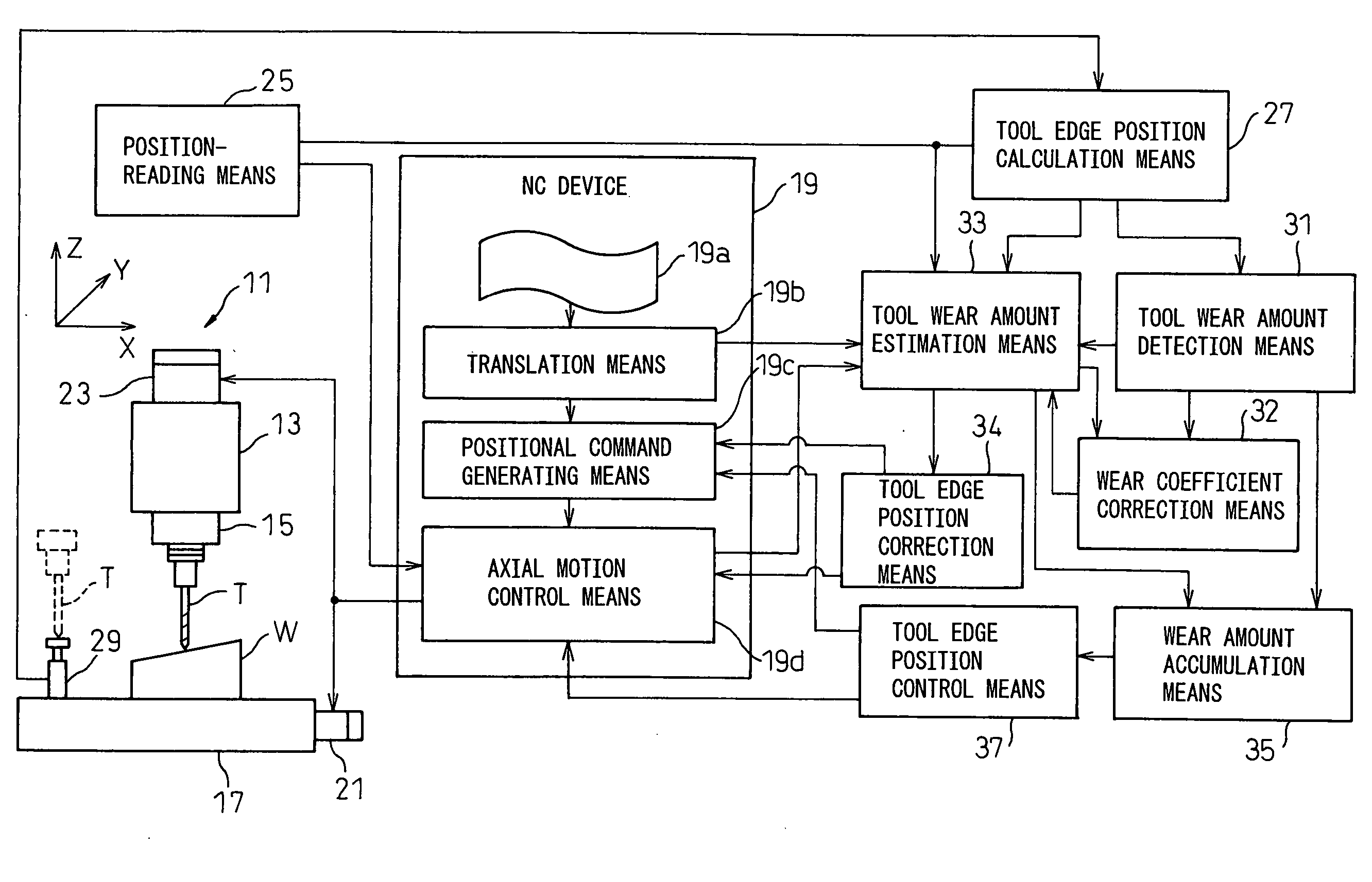
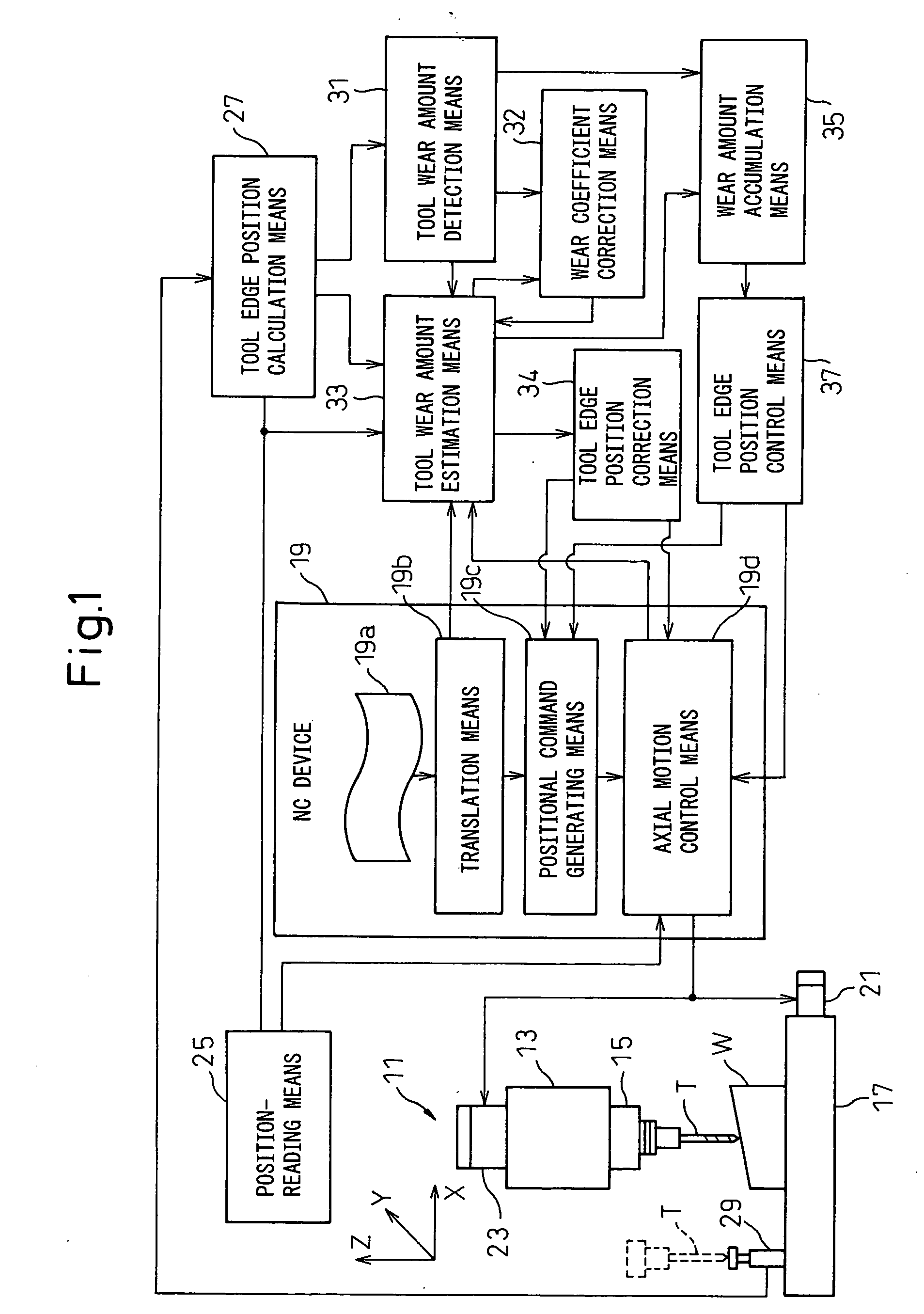
[0019] An embodiment of the present invention will be described with reference to the drawings. In this regard, in the following description, a “desirable machined profile” means a desired profile of a workpiece after being machined; an “actual machined profile” means a profile of the actual workpiece obtained by the machining operation; a “reference machining program” means a machining program prepared so that the desirable machined profile can be obtained on the premise that the working tool T would not be worn during the machining operation and maintains a constant length; and a “modified machining program” means a program obtained by modifying the reference machining program in consideration of the deviation caused by the wear of the working tool T between the desirable machined profile and the actual machined profile.

[0020] First, a main part of a configuration of an NC machine tool 11, provided with a function for correcting the wear of a working tool according to the present...


PUM

PropertyMeasurementUnit
wear coefficientaaaaaaaaaa

Abstract

A wear amount of a working tool T during the machining of a workpiece is estimated during the machining, and a positional command generated in accordance with a predetermined machining program is sequentially corrected during the machining based on the estimated wear amount of the working tool T. The workpiece W is machined in accordance with the corrected positional command. Also, the wear amount of the working tool T upon the interruption of the machining operation is calculated, and the positional command generated in accordance with the predetermined machining program is corrected based on the calculated wear amount of the working tool so that a tool edge position of the working tool T upon the interruption of the machining operation coincides with the tool edge position of the working tool T upon the restart of the machining operation when the machining operation is restarted at a position where the machining operation has been interrupted. The workpiece is machined in accordance with the corrected positional command.

Description

TECHNICAL FIELD [0001] The present invention relates to a method for machining a workpiece, while taking a wear amount of a working tool, and to a machine tool having a function for compensating for a wear amount of a working tool. BACKGROUND ART [0002] In an NC machining tool, a workpiece placed on a table is machined by moving a working tool, mounted to a spindle, and the workpiece relative to each other in accordance with a desirable machining program, whereby a shape of the workpiece obtained by the machining is determined by the trajectory of the working tool. Generally, the machining program is prepared on the premise that the working tool is not worn and maintains a constant length during the machining. [0003] However, in practice, as the machining operation progresses, the working tool wears to shorten its length. Accordingly, as shown, for example, in FIG. 5, when the desired profile 41 of the workpiece is slanted upwards from left to right, the actually machined profile (i...

Claims


Application Information

Patent Timeline
Patent Type & Authority Applications(United States)
IPC IPC(8): B23C1/16G06F19/00
CPCB23Q15/16B23Q15/28B23Q17/09B23Q17/2233Y10T409/30112Y10T409/300896Y10T409/306832Y10T409/303752G05B19/404
Inventor YOSHIDA, JUNKAWANA, AKIRAKURAHASHI, YASUHIRO
Owner MAKINO MILLING MASCH CO LTD
Why Eureka
Try Eureka