
Electrochemical device and method of manufacturing the same

a technology of electrochemical devices and manufacturing methods, which is applied in the direction of sustainable manufacturing/processing, nickel accumulators, cell components, etc., can solve the problems of complicating the manufacturing process, and increasing the number of components, and achieves the effect of little positional deviation

Inactive Publication Date: 2009-01-29
TAIYO YUDEN KK
View PDF4 Cites 23 Cited by
  • Summary
  • Abstract
  • Description
  • Claims
  • Application Information

AI Technical Summary

Benefits of technology

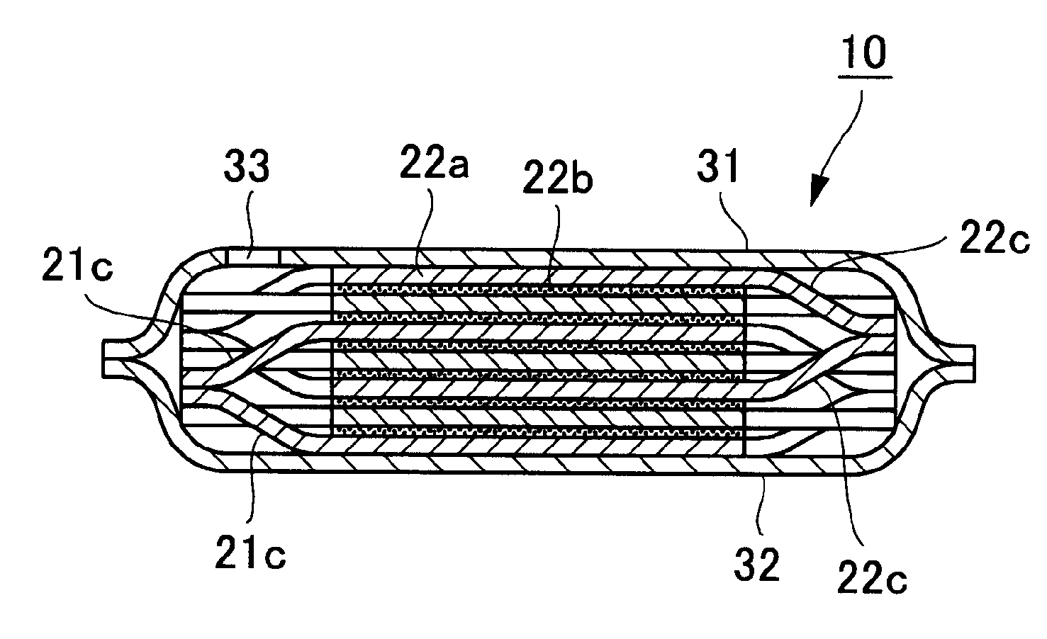
[0011]Accordingly, it is an object of at least one embodiment of the present invention to provide an electrochemical device which produces little positional deviation when electrodes and separators are alternately laminated and which can be manufactured by a roll-to-roll process, and also provide a method for manufacturing the device.
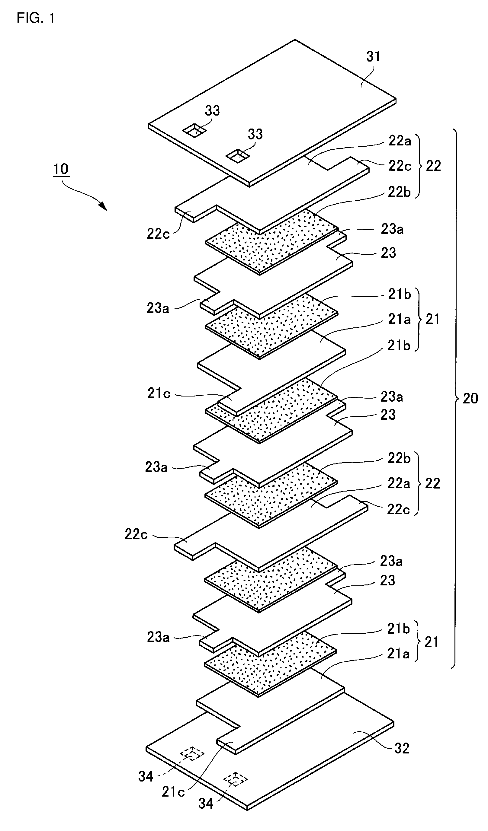
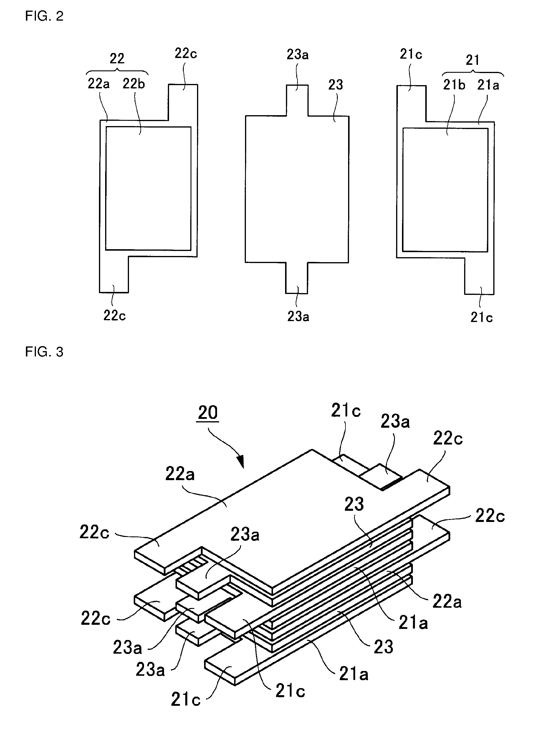
[0013]In the electrochemical device of an embodiment of the present invention, the projections of the electrodes of one of the polarities are connected to each other, and thus the electrodes of the other polarity and the separators disposed between the electrodes of one of the polarities are supported by the electrodes of one of the polarities in a crossing manner. Similarly, the projections of the electrodes of the other polarity are connected to each other, and thus the electrodes of one of the polarities and the separators disposed between the electrodes of the other polarity are supported by the electrodes of the other polarity in a crossing manner. Therefore, in the course of or after the manufacturing process, the laminated electrodes and separators are positionally little deviated, thereby providing an electrochemical device with high reliability.
[0014]In manufacture by a roll-to-roll process using an electrode sheet, the sheet is punched so that the projections of the electrodes are connected via connecting straps, thereby permitting the supply of the sheet while supporting both ends thereof and the stable supply of the sheet.
[0016]Also, in any of the foregoing embodiments, it is preferred that the projections of the separators are aligned in the lamination direction and connected to each other. Since the projections of the separators are connected to each other, the movement of the electrodes and the separators can be further restricted, thereby increasing the effect of preventing positional deviation of the overlap positions.
[0020]In the method for manufacturing the electrochemical device of an embodiment of the present invention, a sheet in which the electrodes are connected through connection straps for connecting the projections is supplied, a sheet in which the separators are connected through connection straps for connecting the projections is supplied. Therefore, the electrode sheet and the separator sheet can be stably securely supplied while both ends of each sheet are supported. In addition, the electrode sheet and the separator sheet are laminated, the resultant laminate is covered with sheets of the sealing member, and the laminate is separated into individual devices, filled with the electrolyte, and sealed with the sealing member or filled with the electrolyte, sealed with the sealing member, and separated into individual devices. Therefore, electrochemical devices can be manufactured by a roll-to-roll process with high workability.

Problems solved by technology

However, the electrochemical device disclosed in Japanese Unexamined Patent Application Publication No. 2006-278897 requires the insulating fixing member for fixing the tab part of each of the collector plates and the tab part of the separator, thereby increasing the number of components and thus causing the problem of complicating the manufacturing process.
In addition, the electrochemical device disclosed in Japanese Patent No. 3531552 requires forming the projection on each separator and engaging together the projections of the adjacent separators, thereby complicating the manufacturing process.
Further, the method of manufacturing a super capacitor disclosed in Japanese Unexamined Patent Application Publication (Translation of PCT Application) No. 2004-515083 includes forming slits for dividing the polarizable electrode from one of the sides of the sheet, thereby failing to support the both sides of the sheet in lamination by roll-to-roll and thus causing the problem of failing to stably support the sheet.

Method used


Image

  • Electrochemical device and method of manufacturing the same
  • Electrochemical device and method of manufacturing the same
  • Electrochemical device and method of manufacturing the same

Examples


example

[0055]The electrochemical device (electric double layer capacitor) shown in FIGS. 1 to 6 was manufactured by the method shown in FIGS. 7 and 8.

[0056]An aluminum foil (manufactured by Toyo Alumi Co., Ltd.) having a thickness of 22 μm was used as each of the current collector sheets 41a and 42a. The sheets 41a and 42a were punched with the dies 51 and 52, respectively, so that the current collectors 21a and 22a of 23.5 mm×15 mm in size are formed when the sheets are finally separated into devices as shown in FIG. 8. The size of the projections 21c and 22c of the current collectors was 3.5 mm×4 mm.

[0057]A porous polyolefin film (manufactured by Nippon Sheet Glass Company, Ltd.) composed of a polyolefin containing an inorganic filler was used as the separator sheet 43a. The sheet 43a was punched with the die 53 as shown in FIG. 7 so that the separators 23 of 23.5 mm×16 mm in size are formed. The size of the projections 23c of the separators was 3 mm×4 mm.

[0058]An aluminum laminate film ...


PUM

PropertyMeasurementUnit
Polarityaaaaaaaaaa
Shapeaaaaaaaaaa

Abstract

An electrochemical device includes four or more electrodes which are laminated with separators provided between the respective electrodes, an electrolyte filled between the respective electrodes, and a sealing member which covers the periphery. The electrodes are arranged so that the polarities alternately change in the lamination direction, and each of the electrodes has projections projecting from diagonally opposite positions on the peripheral edge so that the positions of the projections of the electrodes of different polarities are opposite to each other in the lateral direction and the projections of the electrodes of the same polarity are aligned and connected with each other.

Description

BACKGROUND OF THE INVENTION[0001]1. Field of the Invention[0002]The present invention relates to an electrochemical device such as a secondary battery, an electric double layer capacitor, or the like and a method of manufacturing the device.[0003]2. Description of the Related Art[0004]So-called electrochemical devices capable of storing electric charge, such as secondary batteries such as a lithium-ion battery and a nickel halide battery, and electrochemical capacitors such as an electric double layer capacitor and a redox capacitor, are widely used in, for example, electric apparatuses such as a cellular phone, a digital still camera, and a notebook-size personal computer, and hybrid electric automobiles.[0005]As this type of conventional electrochemical device, for example, Japanese Unexamined Patent Application Publication No. 2006-278897 discloses an electrochemical device including a pair of current collector plates each having a main part and a tab part and disposed so that th...

Claims


Application Information

Patent Timeline
IPC IPC(8): H01M2/16H01M10/04H01G11/00H01G11/10H01G11/12H01G11/22H01G11/24H01G11/38H01G11/42H01G11/52H01G11/66H01G11/72H01G11/84H01M10/30H01M50/417H01M50/423H01M50/426H01M50/429H01M50/463
CPCH01G9/016Y10T29/4911H01G9/155H01G11/12H01G11/72H01G11/80H01G11/84H01M2/162H01M2/1653H01M2/1673H01M2/18H01M4/70H01M10/0525Y02E60/13Y02T10/7011Y02T10/7022Y02E60/124H01G9/058Y02T10/70Y02E60/10H01G11/74H01G11/22H01M50/44H01M50/46H01M50/463Y02P70/50H01M50/429H01M50/417H01M50/423H01M50/426
Inventor HAGIWARA, NAOTOISHIDA, KATSUEI
Owner TAIYO YUDEN KK
Learn More