Improved air pump magnetic rod fixing structure

A fixed structure and improved technology, applied in the direction of pumps, pump devices, pump components, etc., can solve the problems of relative position deviation, magnetic bar working position deviation, affecting the working efficiency and performance of air pumps, etc., to ensure performance and reduce relative The effect of positional deviation

Pending Publication Date: 2020-11-03
广东海利集团有限公司
View PDF0 Cites 0 Cited by
  • Summary
  • Abstract
  • Description
  • Claims
  • Application Information

AI Technical Summary

Problems solved by technology

Therefore, during the working process of the air pump, the working position of the magnetic rod will be affected by the external force due to the softness and hardness of the cup. The relative position of the magnetic rod and the motor will deviate, which will affect the working efficiency and performance of the air pump.

Method used


Image

  • Improved air pump magnetic rod fixing structure
  • Improved air pump magnetic rod fixing structure
  • Improved air pump magnetic rod fixing structure

Examples


Embodiment Construction

[0017] The present invention will be further described below in combination with specific embodiments. Wherein, the accompanying drawings are only for illustrative purposes, showing only schematic diagrams, rather than physical drawings, and should not be construed as limitations on this patent; in order to better illustrate the embodiments of the present invention, some parts of the accompanying drawings will be omitted, Enlargement or reduction does not represent the size of the actual product; for those skilled in the art, it is understandable that certain known structures and their descriptions in the drawings may be omitted.

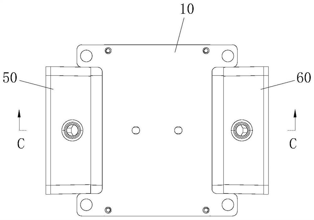
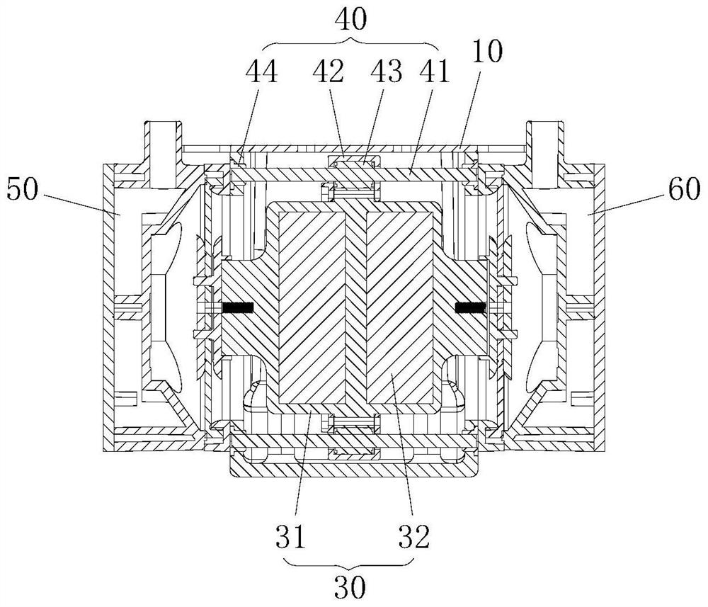
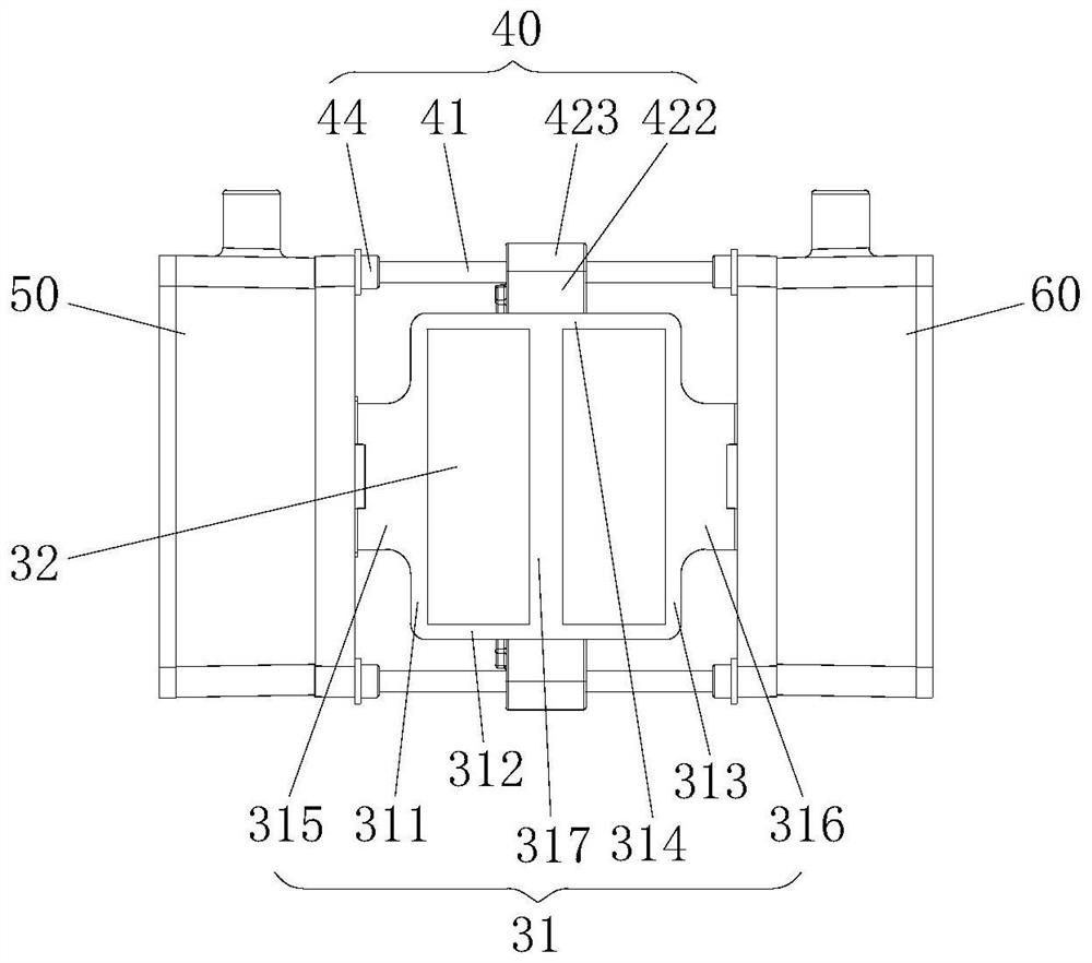
[0018] Such as Figure 1 to Figure 4 Shown is an embodiment of the improved air pump magnetic rod fixing structure of the present invention, including a pump housing 10, a motor 20, a magnetic rod 30, a guide mechanism 40, a first cylinder assembly 50 and a second cylinder assembly 60; the motor 20 and the magnetic rod 30 Set in the pump casing 10,...


PUM


Abstract

The invention relates to the technical field of air pumps, in particular to an improved air pump magnetic rod fixing structure. The structure comprises a pump shell, a motor, a magnetic rod, a guide mechanism, a first air cylinder assembly and a second air cylinder assembly. The motor and the magnetic rod are arranged in the pump shell, and the two ends of the magnetic rod are connected with the first air cylinder assembly and the second air cylinder assembly which are arranged at the two ends of the pump shell respectively. The guide mechanism is fixed in the pump shell and connected with themagnetic rod, and the magnetic rod is driven by the motor to do reciprocating linear motion along the guide mechanism. According to the improved air pump magnetic rod fixing structure, the guide mechanism is arranged to be connected with the magnetic rod, so that when the motor drives the magnetic rod to work, the magnetic rod is limited to reciprocate at a certain position, the distance betweenthe magnetic rod and the motor can be fixed, a fixed gap between the magnetic rod and the motor is ensured when an air pump works, the relative position deviation of the magnetic rod and the motor isreduced to the greatest extent, so that the performance of the air pump is ensured.

Description

technical field [0001] The invention relates to the technical field of air pumps, and more particularly, to an improved fixing structure for magnetic rods of air pumps. Background technique [0002] The diaphragm air pump is a reciprocating pump that relies on the diaphragm to reciprocate in the cylinder to compress and deliver gas. The magnetic rod of the traditional diaphragm air pump is generally fixedly connected to the cylinder assembly through a leather cup, and the material of the leather cup is usually rubber, so the fixing method of the magnetic rod is a soft fixation. Therefore, during the working process of the air pump, the working position of the magnetic rod will be affected by the external force due to the softness and hardness of the cup, and the relative position between the magnetic rod and the motor will be deviated, thereby affecting the working efficiency and performance of the air pump. Contents of the invention [0003] The present invention provide...

Claims


Application Information

Patent Timeline
Patent Type & Authority Applications(China)
IPC IPC(8): F04B45/047F04B39/14F04B41/06
CPCF04B39/14F04B41/06F04B45/043F04B45/047
Inventor 陈俊平
Owner 广东海利集团有限公司
Why Eureka
Try Eureka