Control apparatus for an internal combustion engine

a control apparatus and internal combustion engine technology, applied in the direction of electric control, combustion-air/fuel-air treatment, instruments, etc., can solve the problem of worsening emissions, and achieve the effect of suppressing the fluctuation of air-fuel ratio and time constant of filtering processing

Active Publication Date: 2010-09-16
TOYOTA JIDOSHA KK
View PDF5 Cites 22 Cited by
  • Summary
  • Abstract
  • Description
  • Claims
  • Application Information

AI Technical Summary

Benefits of technology

[0013]Accordingly, one of the objects of the present invention is to provide a control apparatus for an internal combustion engine which effectively avoid a large deviation of the air-fuel ratio of the engine from a target air-fuel ratio, by controlling the feedback correction coefficient and the purge correction coefficient to be appropriate values after a purge control valve closing instruction timing at which an instruction signal is provided to the purge control valve, the instruction signal being a signal to change a condition of the purge control valve from a condition in which the purge control valve is opened to a condition in which the purge control valve is completely closed.
[0040]Therefore, the purge correction amount (see a solid line shown in (C) of FIG. 3) calculated based on the evaporated fuel gas concentration learning value and the estimated purge flow becomes a value which compensates for the evaporated fuel introduced into the combustion chamber precisely after the purge control valve closing instruction timing tpc. Thus, as shown by a solid line in (D) of FIG. 3, the feedback correction amount hardly deviates from the base value “1” for a period immediately after the purge control valve closing instruction timing tpc. As a result, as shown by a solid line in (E) of FIG. 3, the fluctuation of the air-fuel ratio after the purge control valve closing instruction timing tpc is suppressed very effectively. Consequently, it is possible to reduce a NOx emission after the purge control valve closing instruction timing tpc.
[0053]That is, the present control apparatus carries out the correction on the feedback correction amount and the correction on the evaporated fuel gas concentration learning value when the engine is operated at the low revolution speed, even if the base air-fuel ratio learning is not completed when the purge control valve closing instruction timing arrives. Thus, if the deviation amount of the base of the air-fuel ratio is relatively small, an amount of variation of the feedback correction amount becomes smaller when the engine is operated at the low revolution speed after the purge control valve closing instruction timing, compared to the case where the correction on the feedback correction amount and the correction on the evaporated fuel gas concentration learning value are prohibited. As a result, it is possible to further suppress the deviation of the air-fuel ratio, compared to the case where the correction on the feedback correction amount and the correction on the evaporated fuel gas concentration learning value are prohibited. In addition, at the low revolution speed, the actual air-fuel ratio does not vary largely due to the correction on the feedback correction amount after the purge control valve closing instruction timing, even if the deviation amount of the base of the air-fuel ratio is relatively large.
[0064]As described above, the partition ratio is determined based on the operation state parameter of the engine. As a result, it is possible to avoid the large fluctuation of the actual air-fuel ratio after the purge control valve closing instruction timing in a case where the base air-fuel ratio learning is not completed.
[0067]As a result, since the purge correction amount after the purge control valve closing instruction timing becomes closer to an appropriate value, it is possible to suppress the fluctuation of the air-fuel ratio after the purge control valve closing instruction timing more effectively.
[0070]For instance, frequency of the high frequency components contained in the feedback correction amount becomes lower, as the load of the engine becomes lower or as the revolution speed of the engine becomes lower. Thus, the time constant of the filtering processing should be increased, as the load of the engine becomes lower or as the revolution speed of the engine becomes lower. On the other hand, if the time constant of the filtering processing is excessively large, a change of the deficiency of the purge correction amount (i.e., deviation with respect to an amount of the evaporated fuel) emerges in the filtered feedback correction amount with long delay. Therefore, if the time constant of the filtering processing is set to be excessively large, the filtered feedback correction amount at the purge control valve closing instruction timing does not represent the deficiency of the purge correction amount with sufficient accuracy. Accordingly, in view of these facts, the filtering means described above adjusts the time constant of the filtering processing based on the operation state parameter(s) of the engine. As a result, the purge correction amount after the purge control valve closing instruction timing becomes closer to an appropriate value, and therefore, it is possible to suppress the fluctuation of the air-fuel ratio after the purge control valve closing instruction timing more effectively.

Problems solved by technology

As a result, the emission becomes worse.

Method used


Image

  • Control apparatus for an internal combustion engine
  • Control apparatus for an internal combustion engine
  • Control apparatus for an internal combustion engine

Examples


first embodiment

a. First Embodiment

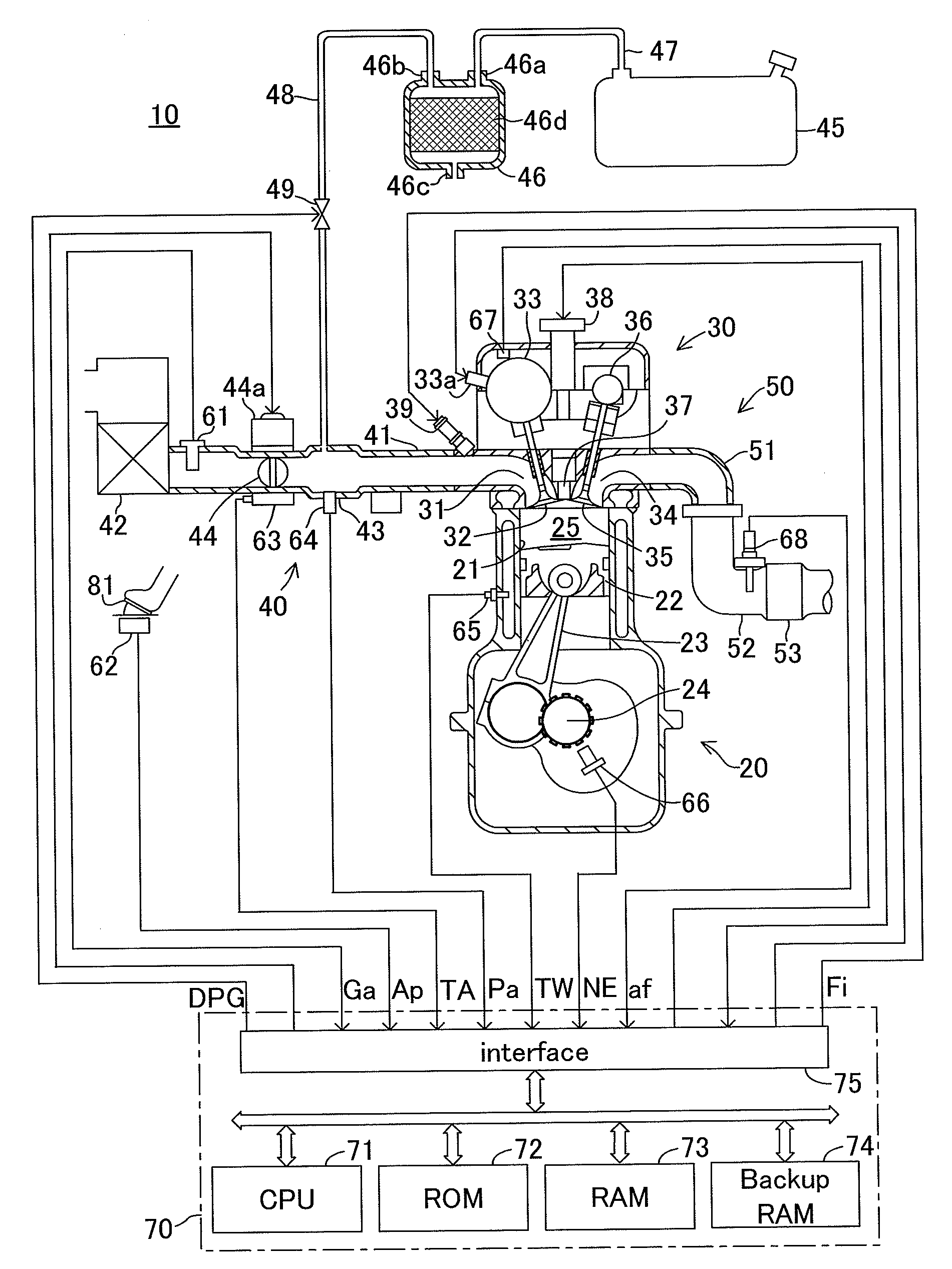
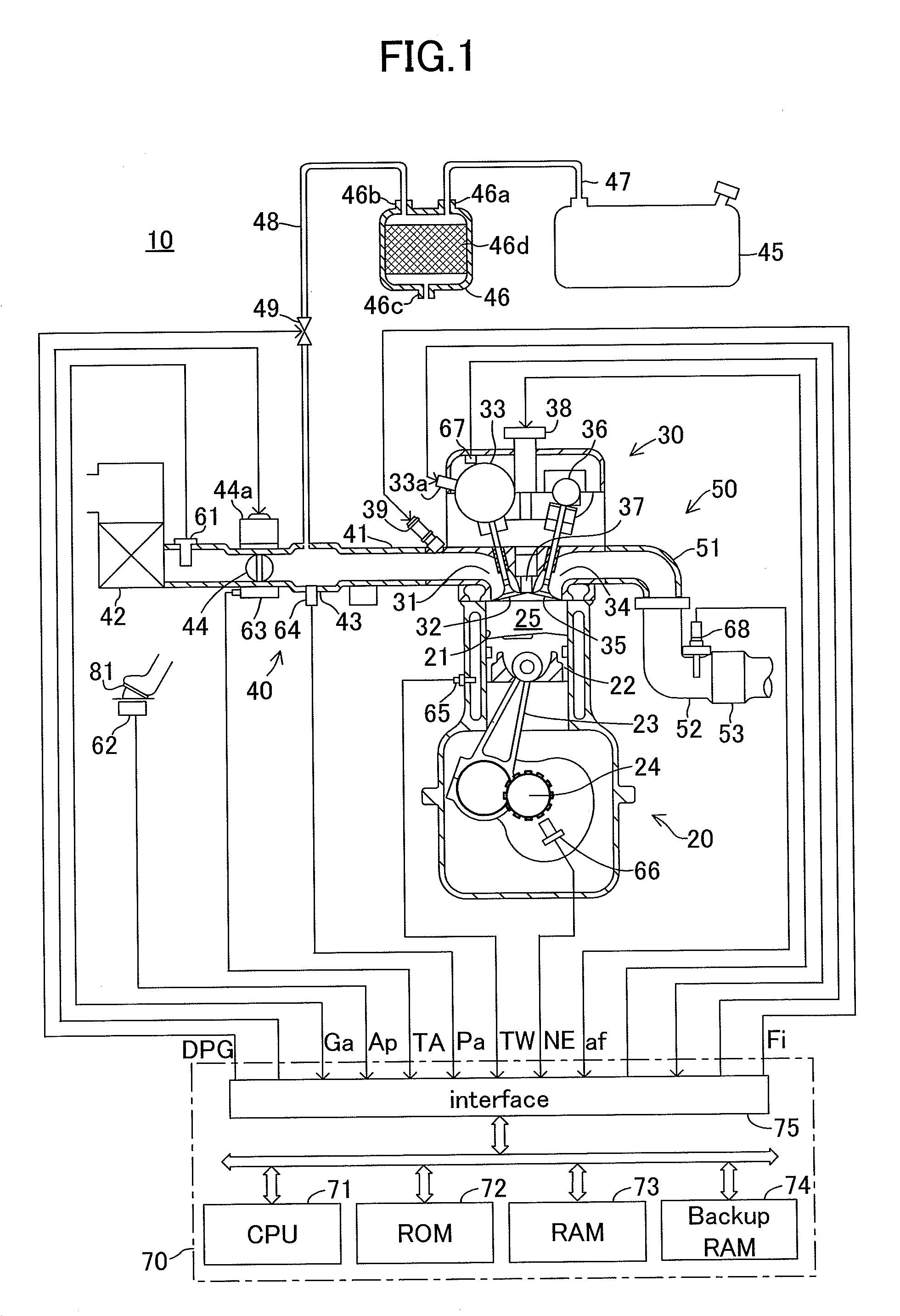
[0090]FIG. 1 shows a schematic configuration of a system in which a control apparatus according to a first embodiment of the present invention is applied to an internal combustion engine 10. The engine 10 is a four-stroke, in-line four cylinder engine. FIG. 1 shows a section of a specific cylinder only, but other cylinders also have a similar configuration.

[0091]The engine 10 includes a cylinder block section 20 including a cylinder block, a cylinder block lower-case, and an oil pan; a cylinder head section 30 fixed on the cylinder block section 20; an intake system 40 for supplying air (fresh air) to the cylinder block section 20; and an exhaust system 50 for discharging exhaust gas from the cylinder block section 20 to the exterior of the engine.

[0092]The cylinder block section 20 includes a cylindrical cylinder 21, a piston 22, a connecting rod 23, and a crankshaft 24. The piston 22 reciprocates within the cylinder 21. The reciprocating motion of the piston 22 ...

second embodiment

b. Second Embodiment

[0229]Next will be described a second embodiment of a control apparatus for the internal combustion engine in accordance with the present invention. The control apparatus according to the second embodiment is different from the control apparatus according to the first embodiment only in that its CPU 71 executes a purge stop timing adjusting routine shown in FIG. 12, instead of the purge stop timing adjusting routine shown in FIG. 11 which the CPU 71 of the first embodiment executes. Hereinafter, the description is made by focusing on this difference. Note that Steps shown in FIG. 12 identical to Steps shown in FIG. 11 have the same numerals as ones shown in FIG. 11.

[0230]The second embodiment, if the base air-fuel ratio learning is not completed when the purge control valve closing instruction timing arrives, prohibits correcting the feedback correction coefficient FAF to the base value “1” at the purge control valve closing instruction timing and correcting the ...

third embodiment

c. Third Embodiment

[0237]Next will be described a third embodiment of a control apparatus for the internal combustion engine in accordance with the present invention. The control apparatus according to the third embodiment is different from the control apparatus according to the first embodiment only in that its CPU 71 executes a purge stop timing adjusting routine shown in FIG. 13, instead of the purge stop timing adjusting routine shown in FIG. 11 which the CPU 71 of the first embodiment executes. Hereinafter, the description is made by focusing on this difference. Note that Steps shown in FIG. 13 identical to Steps shown in FIG. 11 have the same numerals as ones shown in FIG. 11.

[0238]The control apparatus according to the third embodiment determines a partition ratio (i.e., taking-in-ratio) RFAF based on the operation state parameter of the engine 10, if it is determined that the base air-fuel ratio learning has not been completed when the purge control valve closing instruction...


PUM


Abstract

An evaporated fuel gas concentration learning section A8 renews an evaporated fuel gas concentration learning value based on a feedback correction amount FAF. An estimated purge rate calculating section A9 estimates, a flow of an evaporated fuel gas introduced into a combustion chamber based on a flow KP of an evaporated fuel gas passing through a purge control valve in consideration of a transportation delay time duration and a behavior of the evaporated fuel gas. An instructed injection amount determining section A10 calculates a purge correction amount based on the evaporated fuel gas concentration learning value and the estimated purge flow. An evaporated fuel gas purge stop timing adjusting section A11, at a purge control valve closing instruction timing, corrects the feedback correction amount to a base value and corrects the evaporated fuel gas concentration learning value so as to add, to the purge correction amount, an amount corresponding to an correction amount to correct the base injection amount provided by the feedback correction amount at a timing immediately before the feedback correction amount is corrected to the base value.

Description

BACKGROUND OF THE INVENTION[0001]1. Technical Field[0002]The present invention relates to a control apparatus for an internal combustion engine in which evaporated fuel is provided to a combustion chamber via a purge passage, a purge control valve, and an intake passage.[0003]2. Background Art[0004]A conventional control apparatus for an internal combustion engine is known, in which evaporated fuel generated in a fuel tank is provided to a combustion chamber through a purge passage with a purge control valve and an intake passage. Providing the evaporated fuel to the combustion chamber is referred to as “evaporated fuel gas purge (or, “evapo-purge” for short)”.[0005]One of such control apparatuses carries out the evaporated fuel gas purge while an air-fuel ratio feedback control is being performed. In the air-fuel ratio feedback control, an air-fuel ratio of a mixture provided to the engine (an air-fuel ratio of the engine) is detected by an air-fuel ratio sensor disposed in an exha...

Claims


Application Information

Patent Timeline
Patent Type & Authority Applications(United States)
IPC IPC(8): F02D41/30
CPCF02D41/0042
Inventor OKAZAKI, SHUNTARO
Owner TOYOTA JIDOSHA KK
Why Eureka
Try Eureka