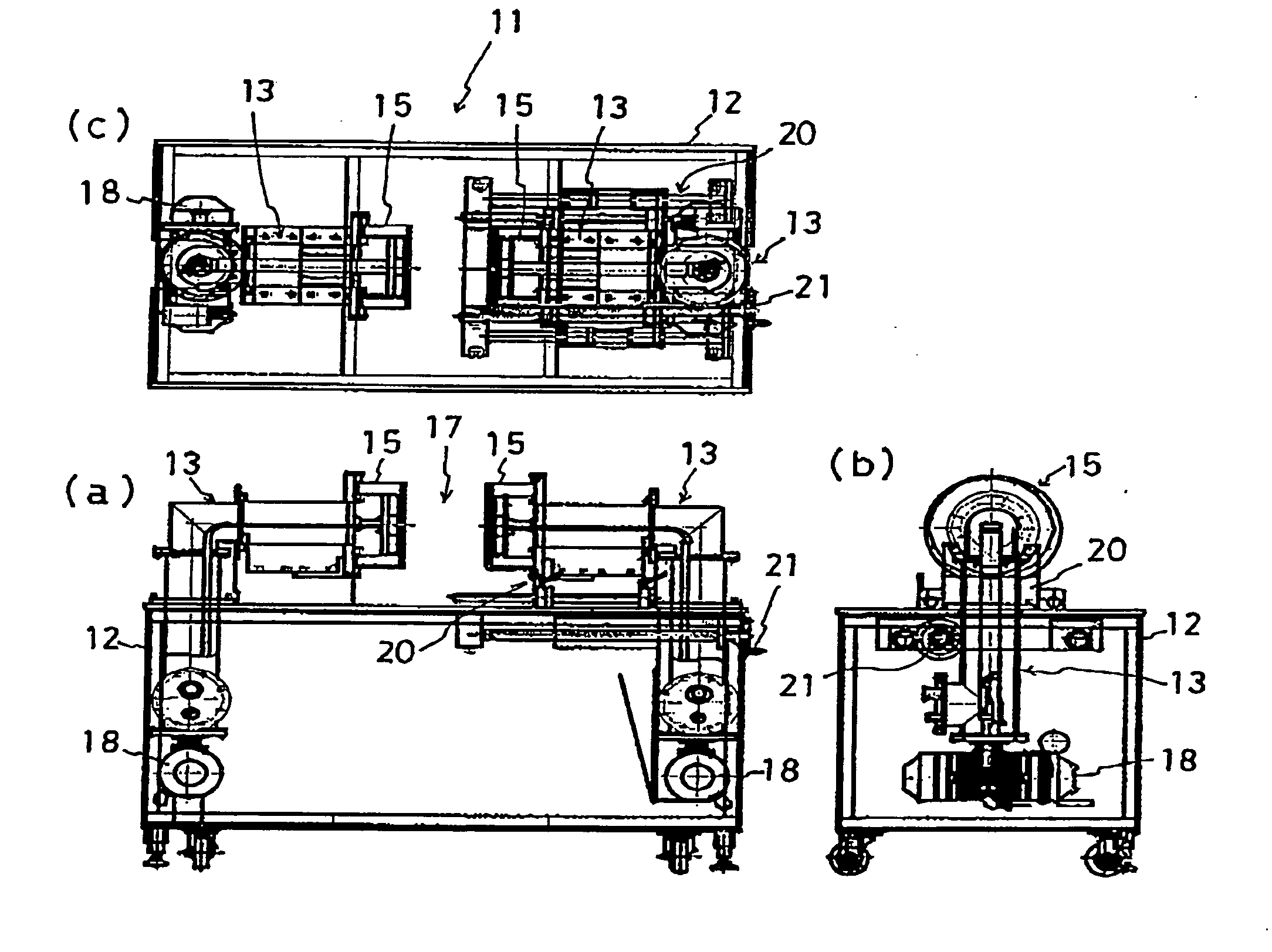
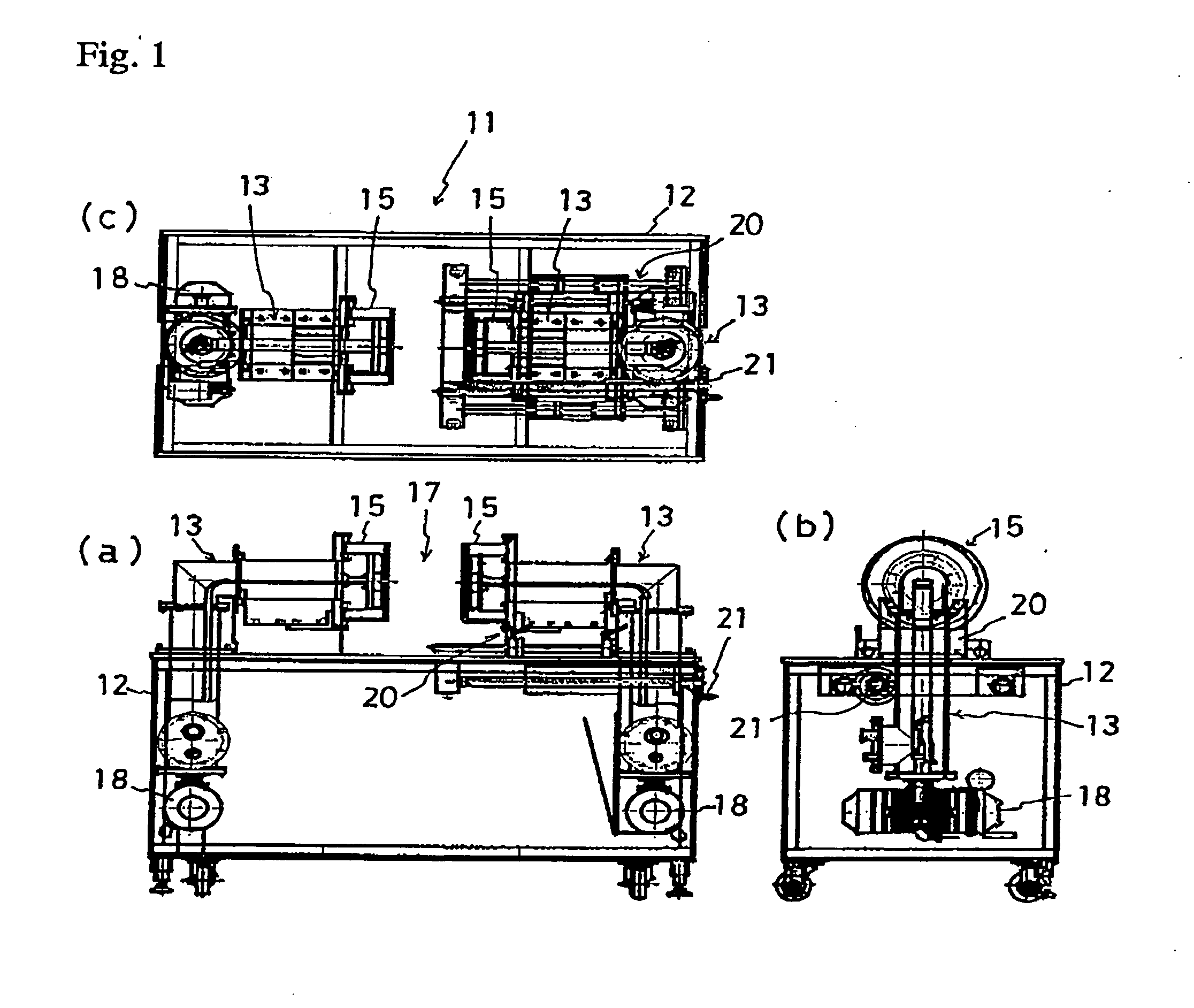
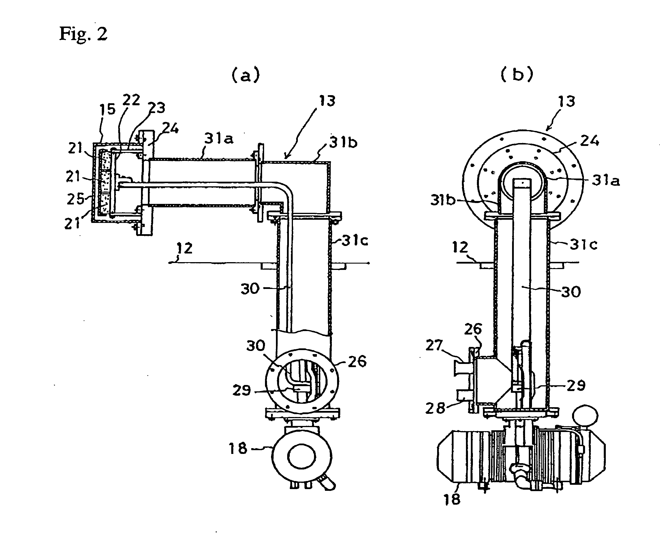
Superconducting permanent magnet

Inactive Publication Date: 2006-11-09
JAPAN SCI & TECH CORP +1
View PDF1 Cites 12 Cited by
  • Summary
  • Abstract
  • Description
  • Claims
  • Application Information

AI Technical Summary

Benefits of technology

[0030] According to this invention, the cooling part of the freezer can provide the bulk superconductors with a lower temperature than that provided by liquid nitrogen, In such a low temperature the bulk superconductors show better superconductivity performance, hence capturing a stronger magnetic field. When the bulk superconductors are cooled, in particular by direct contact or by indirect contact via a heat conveying member with the cooling part of a freezer, the resultant cooling system is far simpler and easier to operate than the conventional one using transfer of liquid helium only.
[0031] Furthermore, Claim 6 provides a superconducting permanent magnet apparatus described in Claim 5, wherein, said freezer is an ultra-low temperature freezer (i) of which constitution is a GM type, a pulse tube type, a Stirling type, a Solvay type, or a combination of a plurality thereof, (ii) which cools and maintains said composite bulk within a temperature range b

Problems solved by technology

However, this apparatus has such a problem that only a small usable space having a strong magnetic field is acquired in the space between the opposing magnetic pole planes of the magnets.
Since the aforementioned bulk superconductor is synthesized by growing large crystals through special heat treatments, there is a limit in its manufacturable sizes.
For instance, it is extremely difficult to synthesize a bulk superconductor (i) which has a large cross-sectional area with a diameter of, for instance, around 100 mm, while (ii) in which c-axes of its crystals are substantially aligned with each other.
Accordingly, it has been extremely difficult to obtain a large magnetic field by synthesizing a single, large-sized bulk superconductor.
Therefore, a large, usable space of magnetic field cannot be practically obtained with a conventional apparatus.
There is further the following problem in the conventional apparatus.
Therefore, when magnetization is done of the bulk superconductor by applying a static magnetic field generated by a superconductor coil, normal operation of a motor constituting

Method used


Image

  • Superconducting permanent magnet
  • Superconducting permanent magnet
  • Superconducting permanent magnet

Examples


Example

[0097] Now, a second embodiment of the present invention will be explained. FIG. 10 shows a magnetic pole assembly in a second embodiment of the present invention, where (a) is a front view, while (b) is a side view. Unlike the first embodiment, the vacuum tube 31 does not extend to the motor portion of the freezer 18, so the freezing part 29 is positioned being separated from the motor portion of the freezer 18. The motor portion and the freezing part 29 of the freezer 18 are connected with a thin pipe 48, so that the freezing part 29 is cooled, resulting in obtaining the same effect as that of the first embodiment.

Example

[0098] Now, a third embodiment will be explained. FIG. 11 is a cross-section view showing a main part of a magnetic pole assembly in a third embodiment. It is not necessary that magnetic pole planes 49 are strictly aligned on the same plane, as is shown in the first embodiment, but it is only necessary that an effective magnetization be done with a magnetic field generated by a single superconducting magnet 39 (not shown).

[0099] In the third embodiment, therefore, magnetic pole planes 49 of the bulk superconductors 21, which constitute the composite bulk 22, may be arranged along a smoothly curved plane like the surface of a cylinder or of a sphere. In this case, as the resultant magnetic field is oriented in some degree to the center of the usable space 17, a rotating machine can be constructed by placing an armature of a rotator, for example, in the usable space 17.

Example

[0100] Now, a fourth embodiment will be explained. FIG. 12 shows plane views for other varieties of arrangement of bulk superconductors 21, in parallel with each other, thus composing a composite bulk. FIG. 12(a) is a plane view for a single-in-line arrangement, (b) is a plane view for a rectangular arrangement, (c) is a plane view for a single-in-line arrangement using a rectangular (square) column type bulk superconductors, while (d) is a plane view for a honeycomb arrangement using a hexagonal column type bulk superconductors.

[0101] Arrangement of the bulk superconductors 21 constituting the composite bulk 22 does not need to have a structure with good symmetry. A plurality of bulk superconductors can be arranged in a single line as is shown in FIG. 12(a), or in a rectangular shape as is shown in FIG. 12(b). A pair of such a composite bulk 22 can be positioned opposing each other at a distance where their respective magnetic fields influence on each other.

[0102] In this case, t...


PUM


Abstract

The present invention provides an apparatus generating a magnetic field, coined a “superconducting permanent magnet apparatus,” that magnetize bulk superconductors into pseudo-permanent magnets, which offer a large, usable space having a strong magnetic field. The superconducting permanent magnet apparatus according to this invention includes: a magnetic pole assembly that holds in a thermally insulated condition, a composite bulk composed of a plurality of bulk superconductors which are arranged in parallel with each other within a vacuum vessel. A stand (i) holds at least a plurality of said magnetic pole assemblies each in a predetermined orientation, and (ii) is movable in a condition that said magnetic pole assemblies are mounted thereon. A cooling part of a freezer is mounted on said magnetic pole assembly. A vacuumizing apparatus being a vacuum pump is connected to said magnetic pole assembly via a vacuum pipe. The composite bulk in said vacuum vessel is fixed to a flange of said magnetic pole assembly to which the vacuum vessel is fixed using a resin-based structural member having a heat-insulating property.

Description

CROSS-REFERENCE TO RELATED APPLICATIONS [0001] The present Application is based on International Application No. PCT / JP2004 / 005909, filed on Apr. 23, 2004, which in turn corresponds to JP 2003-122288 filed on Apr. 25, 2003, and priority is hereby claimed under 35 USC §119 based on these applications. Each of these applications are hereby incorporated by reference in their entirety into the present application.FIELD OF THE INVENTION [0002] The present invention relates to an apparatus generating a magnetic field that enables bulk superconductors—in the superconductive condition thereof—capture a magnetic field, then, that utilizes the bulk superconductors as a magnet. BACKGROUND OF THE INVENTION [0003] As a conventional means for obtaining a usable space with a strong magnetic field, disclosed in Patent Document 1 is an apparatus that, while cooling a bulk superconductor by connecting it via a heat conveying member with a cooling part of a freezer, magnetizes the bulk superconductor ...

Claims


Application Information

Patent Timeline
IPC IPC(8): H01L39/24H01F6/00H01F6/04H01F7/20
CPCH01F7/202H01F6/00
Inventor OKA, TETSUONOTO, KOSHICHIYOKOYAMA, KAZUYA
Owner JAPAN SCI & TECH CORP
Why Eureka
Try Eureka