Flight control surface actuation system with redundantly configured actuator assemblies

a technology of actuators and flight control surfaces, applied in the direction of aircraft stabilisation, power amplification, aircraft power plants, etc., can solve the problems of system drawbacks, inability to move the flight control surface sufficiently to compensate for the inoperableness, and inoperable flight control surface actuators

Inactive Publication Date: 2006-11-16
HONEYWELL INT INC
View PDF25 Cites 30 Cited by
  • Summary
  • Abstract
  • Description
  • Claims
  • Application Information

AI Technical Summary

Benefits of technology

[0007] The present invention provides a flight control surface actuation system redundancy mechanism that allows one or more actuators to effect full and continued flight control surface movement in the unlikely event that one or more additional actuators that are coupled to the same flight control surface become inoperable.

Problems solved by technology

Though unlikely, it is postulated that a flight control surface actuator could become inoperable.
Although flight control surface actuation systems, such as the one generally described above, operate safely, reliably, and robustly, these systems can suffer certain drawbacks.
For example, for some types of actuators, if the actuator is rendered inoperable, the remaining actuators that are coupled to the same flight control surface may not be able to move the flight control surface sufficiently to compensate for the inoperability.
If the flight control surface is in a position other than in a neutral position during such an event, the aircraft may be difficult to handle.
Hence, there is a need for a system and method that will not prevent or inhibit an actuator from moving a flight control surface in the unlikely event that another actuator that is coupled to the same flight control surface becomes inoperable.

Method used


Image

  • Flight control surface actuation system with redundantly configured actuator assemblies
  • Flight control surface actuation system with redundantly configured actuator assemblies
  • Flight control surface actuation system with redundantly configured actuator assemblies

Examples


Embodiment Construction

[0015] The following detailed description is merely exemplary in nature and is not intended to limit the invention or the application and uses of the invention. Furthermore, there is no intention to be bound by any theory presented in the preceding background or the following detailed description.

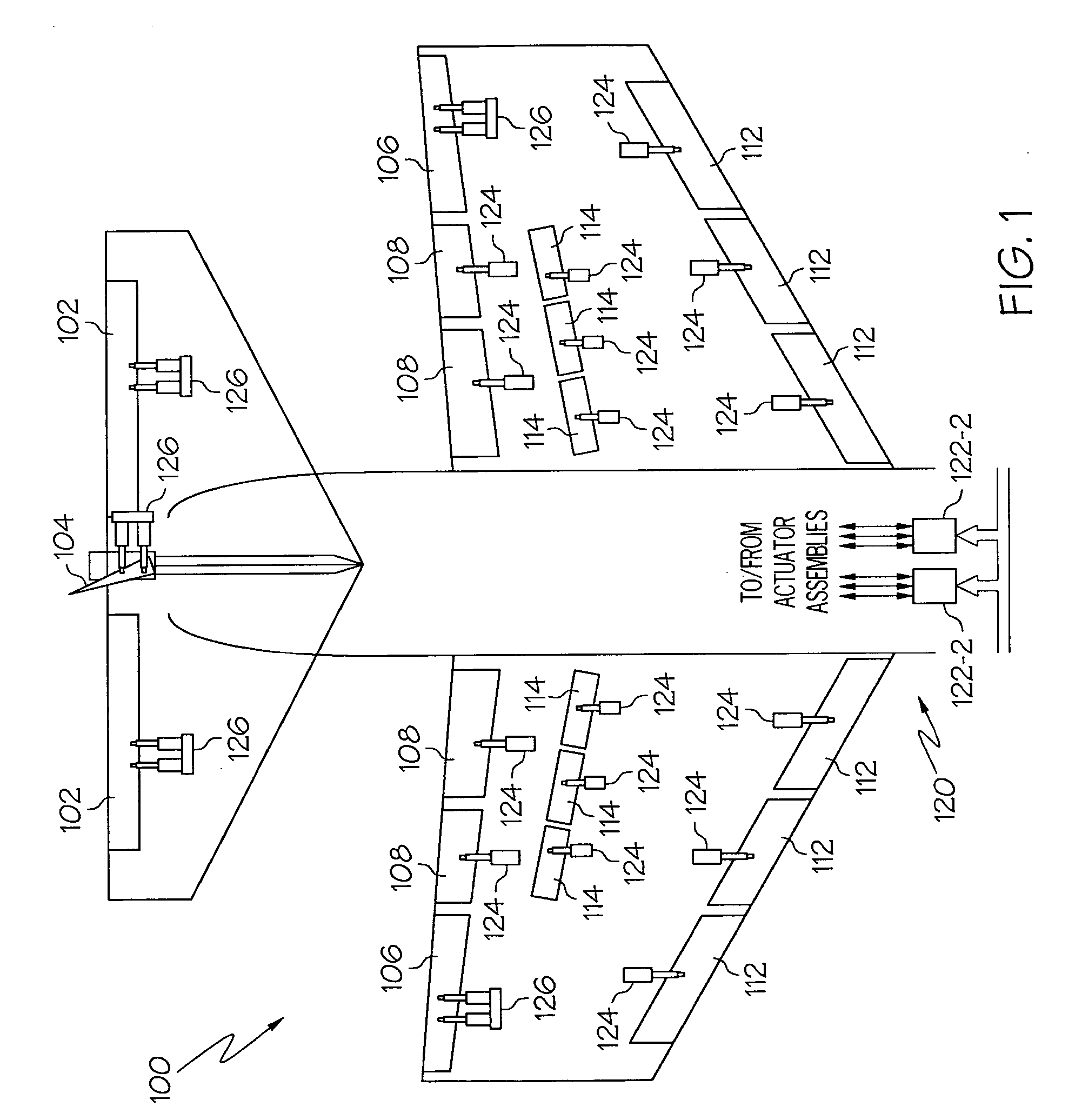
[0016] Turning first to FIG. 1, a schematic diagram of a portion of an exemplary aircraft and an exemplary flight control surface actuation system is shown. In the illustrated embodiment, the aircraft 100 includes a pair of elevators 102, a rudder 104, and a pair of ailerons 106, which are the primary flight control surfaces, and a plurality of flaps 108, slats 112, and spoilers 114, which are the secondary flight control surfaces. The primary flight control surfaces 102-106 control aircraft movement about the aircraft pitch, yaw, and roll axes. Specifically, elevators 102 are used to control aircraft movement about the pitch axis, the rudder 104 is used to control aircraft movement about ...


PUM


Abstract

A flight control surface actuator assembly includes a plurality of flight control surface actuators, and a pivot arm. Each flight control surface actuator is adapted to couple to a flight control surface, and each is further adapted to receive a drive force and is operable, upon receipt thereof, to move between at least an extended position and a retracted position. The pivot arm is rotationally coupled to, and is configured to pivot relative to, each of the flight control surface actuators, the pivot arm is also adapted to be rotationally coupled to, and configured to pivot relative to, a static airframe structure.

Description

CROSS-REFERENCES TO RELATED APPLICATIONS [0001] This application claims the benefit of U.S. Provisional Application No. 60 / 680,073 filed May 11, 2005.TECHNICAL FIELD [0002] The present invention relates to flight control surface actuation and, more particularly, to a flight control surface actuation system that includes redundantly configured actuator assemblies. BACKGROUND [0003] Aircraft typically include a plurality of flight control surfaces that, when controllably positioned, guide the movement of the aircraft from one destination to another. The number and type of flight control surfaces included in an aircraft may vary, but typically include both primary flight control surfaces and secondary flight control surfaces. The primary flight control surfaces are those that are used to control aircraft movement in the pitch, yaw, and roll axes, and the secondary flight control surfaces are those that are used to influence the lift or drag (or both) of the aircraft. Although some airc...

Claims


Application Information

Patent Timeline
Patent Type & Authority Applications(United States)
IPC IPC(8): B64C13/00
CPCB64C13/42B64C13/00B64C13/341B64C13/504B64C13/505
Inventor WINGETT, PAUL T.POTTER, CALVIN C.HANLON, CASEYBENSON, DWAYNE M.
Owner HONEYWELL INT INC
Why Eureka
Try Eureka