Column capillary seal for FDB motors

a technology of capillary seals and motors, which is applied in the direction of shafts, bearings, dynamo-electric machines, etc., can solve problems such as prone to fluid loss

Inactive Publication Date: 2006-11-16
SEAGATE TECH LLC
View PDF18 Cites 20 Cited by
  • Summary
  • Abstract
  • Description
  • Claims
  • Application Information

AI Technical Summary

Problems solved by technology

Such capillary seals often have a relatively large cross-sectional area exposed to an ambient

Method used


Image

  • Column capillary seal for FDB motors
  • Column capillary seal for FDB motors
  • Column capillary seal for FDB motors

Examples


Embodiment Construction

[0025] The following description is presented to enable a person of ordinary skill in the art to make and use various aspects of the inventions. Descriptions of specific materials, techniques, and applications are provided only as examples. Various modifications to the examples described herein will be readily apparent to those skilled in the art, and the general principles defined herein may be applied to other examples and applications without departing from the spirit and scope of the inventions. For example, aspects and examples may be employed in a variety of motors, including motors for use in disc storage drives. Motors for disc storage drives may be designed and may operate in a number of ways. The exemplary motors and other exemplary subject matter provided herein are for illustrating various aspects and are not intended to limit the range of motors and devices in which such examples and aspects may be applied.

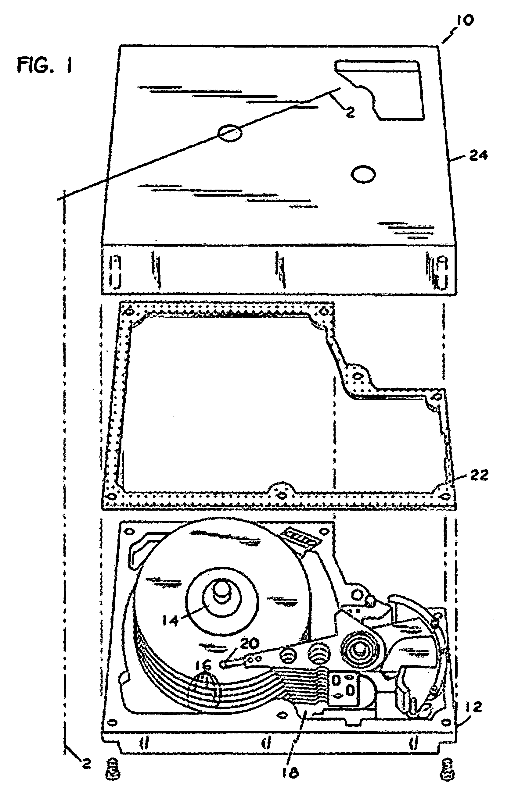
[0026] Turning briefly to FIG. 1, a plan view of an exemplary m...


PUM


Abstract

For a motor having liquid lubricated bearing surface(s), aspects include providing a column shaped Capillary Seal (CS) for storing and supply lubricating liquid to the bearing surface(s). The column shaped CS may have a cross-section substantially topologically equivalent to a circle. Aspects include disposing the column shaped CS between relatively rotational motor members or between relatively irrotational motor members. Other aspects include disposition of the column shaped CS in a spiral shape where one opening of the CS fluidicly communicates with the bearing surface and another opening vents to a gas environment. Still other aspects include disposing the column shaped CS circumferentially on surfaces of generally cylindrical shaped motor members. Such surfaces may oppose a second surface that is one of relatively rotational and relatively irrotational vis the surface. The column shaped CS may circumscribe an axis of a rotating member or may be disposed parallel to the axis of the rotating member.

Description

BACKGROUND [0001] 1. Field [0002] The present invention relates generally to seals for Fluid Dynamic Bearing (FDB) motors and more particularly to capillary seals and lubricating liquid reserviors for use in FDB motors. [0003] 2. Description of Related Art [0004] Capillary seals are presently used to retain lubricating liquid (e.g., oil) at hydrodynamic bearing surfaces of disc drive motors and to provide a reservoir of lubricating liquid sufficient to maintain lubrication of hydrodynamic bearing surfaces throughout an expected lifetime of the disc drive. [0005] Typical capillary seals are formed between radially opposing surfaces of coaxially disposed relatively rotating members of a disc drive motor, e.g., between an outer surface of a fixed shaft and an inner surface of a rotating hub disposed around the shaft. Typically, either the shaft or the hub is machined so that the radially opposing surfaces taper with respect to each other and thereby form a capillary seal with an annula...

Claims


Application Information

Patent Timeline
IPC IPC(8): H02K5/16
CPCF16C33/107H02K7/085H02K5/1675F16C33/74
Inventor FLORES, PACOAIELLO, ANTHONY J.KLOEPPEL, KLAUS D.GRANTZ, ALAN L.
Owner SEAGATE TECH LLC
Why Eureka
Try Eureka