Fluid Dynamic Pressure Bearing, Spindle Motor Provided with Fluid Dynamic Pressure Bearing, and Recording Disk Drive Device Provided with Spindle Motor

a technology of dynamic pressure bearing and spindle motor, which is applied in the direction of sliding contact bearings, mechanical devices, dynamo-electric components, etc., can solve the problems of increasing the electric consumption of the motor, difficult to achieve a predetermined bearing stiffness, and difficulty in reducing the size and thickness of the spindle motor, so as to reduce the size and thickness of the motor

Inactive Publication Date: 2006-03-09
NIPPON DENSAN CORP
View PDF7 Cites 12 Cited by
  • Summary
  • Abstract
  • Description
  • Claims
  • Application Information

AI Technical Summary

Benefits of technology

[0019] According to the present invention, it is possible to secure the bearing stiffness of each of a radial dynamic pressure bearing and a thrust dynamic pressure bearing and the axial dimension of a capillary seal, and further, reduce in size and thickness of a motor as a whole.

Problems solved by technology

As a consequence, it has been very difficult to reduce the spindle motor in size and thickness while maintaining the required rotational accuracy in the above-described motor.
As a result, it has been difficult to achieve a predetermined bearing stiffness.
If oil having a high viscosity is used in order to avoid such a decrease in viscosity of the oil, the viscosity has become excessively high in a low temperature ambience, so that a rotational load of the motor is increased, thereby increasing an electric consumption by the motor.
In this case, the flowing-out oil may adhere to a hard disk on a side of the drive device or a magnetic head disposed near the hard disk, thereby causing a reading / writing error.

Method used


Image

  • Fluid Dynamic Pressure Bearing, Spindle Motor Provided with Fluid Dynamic Pressure Bearing, and Recording Disk Drive Device Provided with Spindle Motor
  • Fluid Dynamic Pressure Bearing, Spindle Motor Provided with Fluid Dynamic Pressure Bearing, and Recording Disk Drive Device Provided with Spindle Motor
  • Fluid Dynamic Pressure Bearing, Spindle Motor Provided with Fluid Dynamic Pressure Bearing, and Recording Disk Drive Device Provided with Spindle Motor

Examples


first embodiment

Structure of Spindle Motor

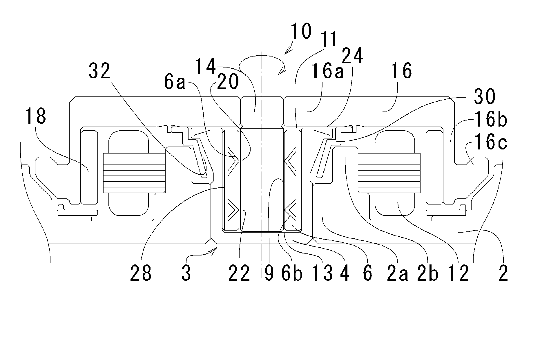
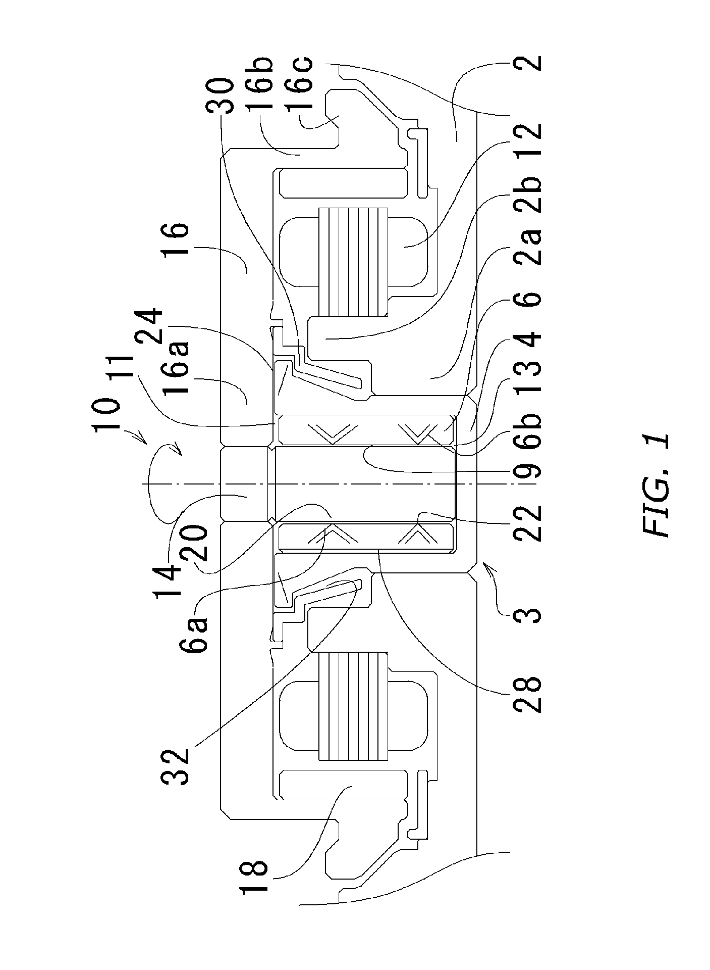
[0036]FIG. 1 is a cross-sectional view showing a spindle motor in a first preferred embodiment according to the invention. As shown in FIG. 1, the spindle motor in the present preferred embodiment basically includes a bracket 2, a bearing member 3 fixed to the bracket 2 and a rotor 10 rotatably supported by the bearing member 3.

[0037] An annular boss 2a is disposed around a center hole, which holds the bearing member 3 therein, at the center of the bracket 2. A cylindrical portion 2b is formed at the boss 2a. A stator 12 is held at the outer periphery of the cylindrical portion 2b by press-fitting and / or bonding, and further, the bearing member 3 is held at the inner circumference thereof by press-fitting and / or bonding.

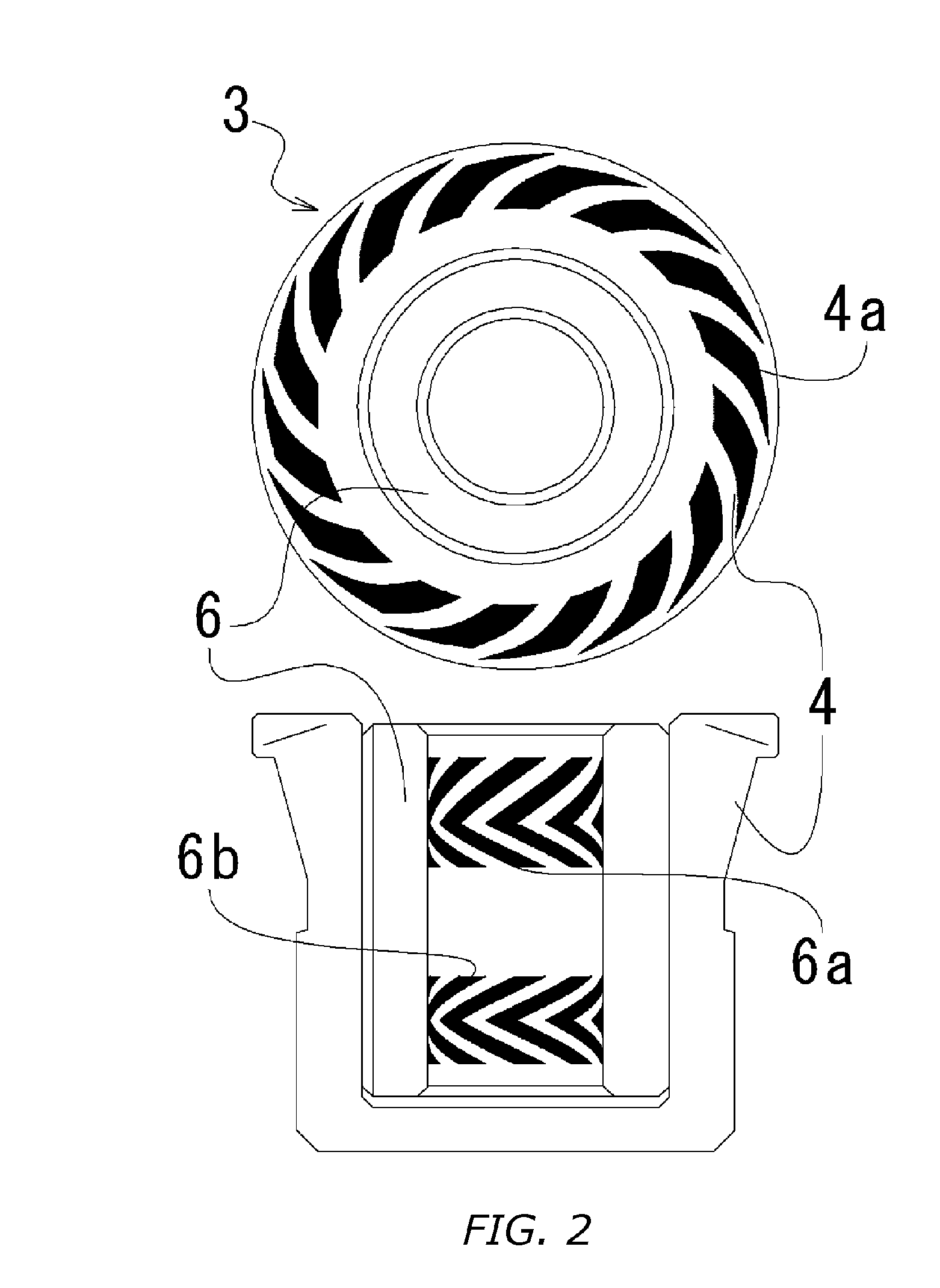
[0038] The bearing member 3 includes a bearing housing 4 and a sleeve 6 held at the inner circumference of the bearing housing 4. The bearing housing 4 is a bottomed cylindrical member opened at the upper portion thereof and is formed by...

second embodiment

[0074]FIG. 5 is an enlarged cross-sectional view showing essential parts of a spindle motor in a second preferred embodiment according to the invention. The basic structure of the spindle motor in the second preferred embodiment is identical to that of the above-described first preferred embodiment, and therefore, corresponding component parts will be designated by reference numerals on the order of 100.

[0075] In FIG. 5, at a lower surface of a rotor upper wall 116a of a rotor hub 116 is formed a projection 116f disposed outward of a bearing housing 104 in a radial direction and projecting downward in an axial direction. To an inner circumference of the projection 116f is fixed an annular member 130 having a connecting portion 130c.

[0076] The annular member 130 is caulked and fixed by plastically deforming a tip of the projection 116f inward in the radial direction after the annular member 130 is fitted to the projection 116f of the rotor hub 116. The caulking may be performed at ...

third embodiment

[0077]FIG. 6 is an enlarged cross-sectional view showing essential parts of a spindle motor in a third preferred embodiment according to the invention. The basic structure of the spindle motor in the third preferred embodiment is identical to that of the above-described first preferred embodiment, and therefore, corresponding component parts will be designated by reference numerals on the order of 200.

[0078] In FIG. 6, at a lower surface of a rotor upper wall 216a of a rotor hub 216 is formed a step 216g disposed outward of a bearing housing 204 in a radial direction and projecting downward in an axial direction. Furthermore, at a lower end of the step 216g is formed a projection 216f projecting downward in the axial direction. To an inner circumference of the projection 216f is fixed an annular member 230 having a engaging portion 230b and a columnar portion 230a.

[0079] The annular member 230 is caulked and fixed by plastically deforming a tip of the projection 216f inward in the...


PUM


Abstract

In a fluid dynamic pressure bearing, a capillary seal (32) is configured in a third fine clearance (11) defined between an upper peripheral surface of a bearing housing (4) and an inner circumferential surface of an annular member (30) fixed onto a rotor upper wall (16a). Furthermore, the annular member (30) is formed by press working.

Description

BACKGROUND OF THE INVENTION [0001] 1. Field of the Invention [0002] The invention relates to a fluid dynamic pressure bearing, a spindle motor provided with the fluid dynamic pressure bearing, and a recording disk drive device provided with the spindle motor. [0003] 2. Background Art [0004] A fluid dynamic pressure bearing, which utilizes a dynamic pressure generated in a lubricating fluid such as oil to be retained in a clearance defined between a shaft and a sleeve during rotation of a motor, has been conventionally used as a bearing in the motor for rotating a recording disk in a hard disk drive device, a removable disk drive device or the like. Various kinds of such fluid dynamic pressure bearings have been proposed heretofore. [0005] As shown in FIG. 9, a motor in the prior art includes a pair of radial bearings 106 arranged separately in an axial direction at a clearance defined between an outer peripheral surface of a shaft 102 and an inner circumferential surface of a sleeve...

Claims


Application Information

Patent Timeline
Patent Type & Authority Applications(United States)
IPC IPC(8): F16C32/06
CPCF16C17/02F16C17/04H02K5/1677F16C33/103H02K5/1675F16C17/107F16C33/745F16C2370/12
Inventor SEKII, YOICHITAMAOKA, TAKEHITO
Owner NIPPON DENSAN CORP
Why Eureka
Try Eureka