High-speed centrifugal seal for a spindle motor

a centrifugal seal and spindle motor technology, applied in the field of spindle motors, can solve the problems of poor resistance to mechanical shock and vibration, damage to the disc drive, data loss, etc., and achieve the effect of improving the strength of the centrifugal seal, reducing the risk of damage, and increasing the shock resistan

Inactive Publication Date: 2007-05-29
SEAGATE TECH LLC
View PDF7 Cites 11 Cited by
  • Summary
  • Abstract
  • Description
  • Claims
  • Application Information

AI Technical Summary

Benefits of technology

[0008]The present invention provides a stable spindle motor having improved robustness and added shock resistance. A high-speed centrifugal capillary seal retains fluid wherein the strength of the centrifugal seal is maximized. A fluid reservoir is positioned between rotatable components and therefore the fluid in the fluid reservoir also rotates at a maximized speed. The invention also provides for fluid recirculation wherein fluid is recirculated through a fluid recirculation passageway, through the motor and substantially around a counterplate.
[0009]The present invention is further directed to reduce power consumption. A single thrust plate that is comparatively small is utilized, reducing power consumption. Also, a comparatively small diameter thrust plate gap is formed. A gain in efficiency is realized and characteristics including surface flatness, run out and perpendicularity are improved. Further, although power consumption is reduced, the present invention is particularly useful for spindle motors supporting a heavy load such as a disc drive having a disc pack and a plurality of discs.
[0010]Features of the invention are achieved in part by utilizing a top cover attach design. The shaft is made more rigid, which adds stability to the entire motor. Further, a high-speed centrifugal capillary seal is provided by forming a centrifugal capillary seal meniscus extending from a rotatable shield to a rotatable counterplate when the motor is rotating.
[0011]The present invention employs a thrust bearing that is inboard of a capillary seal. Further, an enlarged fluid reservoir is positioned between the counterplate and shield. The present invention employs a novel design in that both a comparatively small thrust plate that reduces power consumption and an enlarged fluid reservoir, positioned axially above the counterplate, is provided together. Further, by utilizing a comparatively small thrust plate, a smaller thrust gap is maintained, and surface flatness, run out and perpendicularity are improved.
[0012]Two thrust surfaces are provided, a first thrust surface on a first side of the thrust plate adjacent to the counterplate, and a second thrust surface on a second side of the thrust plate adjacent to the sleeve. The first thrust surface provides a thrust force in a direction that generally forces the counterplate and sleeve axially up, and the second thrust surface provides a thrust force in an opposite direction that generally forces the sleeve axially down. These thrust forces maintain proper axial positioning of the motor components and also maintain motor axial stiffness.

Problems solved by technology

A slight wobble or run-out in disc rotation can cause the disc to strike the read / write head, possibly damaging the disc drive and resulting in loss of data.
Imperfections in the raceways and ball bearing spheres result in vibrations.
Also, resistance to mechanical shock and vibration is poor in the case of ball bearings, because of low damping.
Vibrations and mechanical shock can result in misalignment between data tracks and the read / write transducer.
These shortcomings limit the data track density and overall performance of the disc drive system.
Because this rotational accuracy cannot be achieved using ball bearings, disc drives currently utilize a spindle motor having fluid dynamic bearings between a shaft and sleeve to support a hub and the disc for rotation.
Further, hydrodynamic bearings can be scaled to smaller sizes whereas ball bearings have smallness limitations.
However, hydrodynamic bearings suffer from sensitivity to external loads or mechanical shock.
Fluid can in some cases be jarred out of the bearing by vibration or shock events.
These particles can deposit on the read / write heads and the surfaces of the discs, causing damage to the discs and the read / write heads as they pass over the discs.
However, with a larger reservoir having diverging walls, the capillary seal gap is widened and thus the oil retention capability is lowered.
Moreover, although a radial capillary provides some shock resistance, its shock resistance is limited and fluid can be dislodged from a reservoir.
Laptop or portable computers can be subjected to large magnitudes of mechanical shock as a result of handling.
Additionally, since motors are being designed having reduced power consumption, maintaining proper axial positioning of motor components is made increasingly difficult.

Method used


Image

  • High-speed centrifugal seal for a spindle motor
  • High-speed centrifugal seal for a spindle motor
  • High-speed centrifugal seal for a spindle motor

Examples


Embodiment Construction

[0021]Exemplary embodiments are described with reference to specific configurations. Those of ordinary skill in the art will appreciate that various changes and modifications can be made while remaining within the scope of the appended claims. Additionally, well-known elements, devices, components, methods, process steps and the like may not be set forth in detail in order to avoid obscuring the invention.

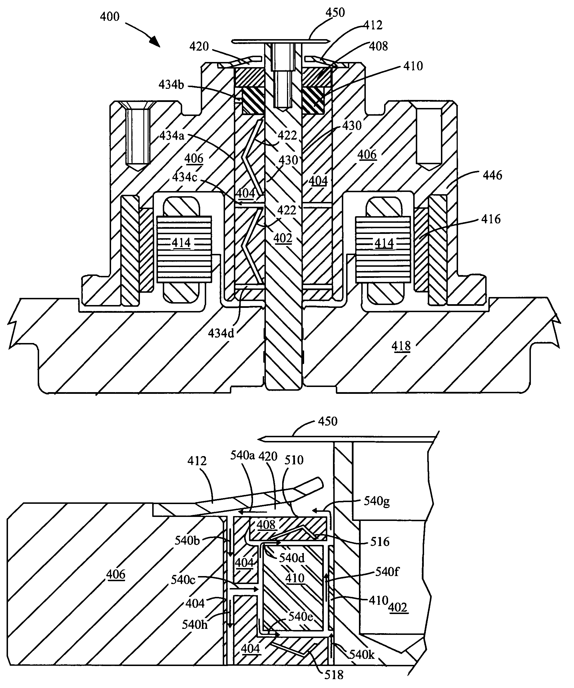
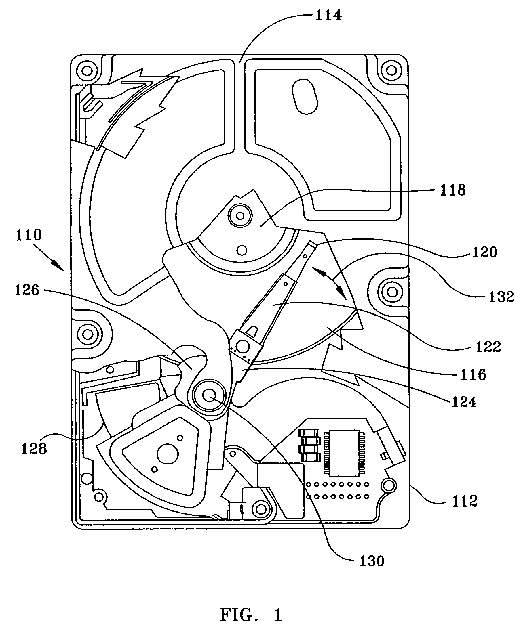
[0022]A system and method is described herein for providing a robust spindle motor having added shock resistance for fluid containment and improved power consumption. The present invention is further useful for maintaining proper axial positioning of motor components in motors supporting heavy loads such as a disk drive memory system having a weighty disc pack.

[0023]It will be apparent that features of the discussion and claims may be utilized with disc drives, low profile disc drive memory systems, spindle motors, various fluid dynamic bearing designs including hydrodynamic and hy...


PUM

PropertyMeasurementUnit
diameteraaaaaaaaaa
thrust forceaaaaaaaaaa
speedaaaaaaaaaa

Abstract

A robust spindle motor is provided having added shock resistance for fluid containment. In an aspect, a high-speed centrifugal capillary seal contains a fluid reservoir extending between similarly rotatable components. Fluid is recirculated through the motor and substantially around a counterplate. Proper axial positioning of motor components and stiffness is maintained in motors supporting heavy loads such as a disk drive memory system having a weighty disc pack. In an aspect, two separate thrust surfaces provide oppositely directed axial forces acting on motor components. In an aspect, a single thrust plate that is comparatively small is utilized, reducing power consumption. Also, a thrust bearing situated inboard of a capillary seal forms a comparatively small diameter thrust plate gap. The comparatively small diameter thrust plate gap increases efficiency and characteristics including surface flatness, run out and perpendicularity are improved.

Description

CROSS REFERENCE TO RELATED APPLICATION[0001]This application is based on a provisional application 60 / 488,226, filed Jul. 16, 2003, attorney docket number STL 3416.01, entitled Rotating Counterplate And Shield For Centrifugal Sealing, and assigned to the Assignee of this application and incorporated herein by reference.FIELD OF THE INVENTION[0002]The invention relates generally to spindle motors, and more particularly to a high-speed capillary seal wherein fluid circulates around a counterplate for a hydrodynamic fluid bearing for use with a heavy load disc drive data storage system.BACKGROUND OF THE INVENTION[0003]Disc drive memory systems are being utilized in progressively more environments, and design and performance needs have intensified including improved robustness and reduced power consumption. Besides traditional computing environments, disc drive memory systems are used more recently by devices including digital cameras, digital video recorders, laser printers, photo copi...

Claims


Application Information

Patent Timeline
Patent Type & Authority Patents(United States)
IPC IPC(8): G11B17/08F16C32/06H02K5/16F16C33/10F16C33/74G11B17/02G11B19/20
CPCF16C17/026F16C17/045F16C33/107F16C33/1085F16C33/74G11B19/2009F16C2370/12
Inventor HERNDON, TROY M.LEBLANC, JEFFRY A.NOTTINGHAM, ROBERT A.
Owner SEAGATE TECH LLC
Why Eureka
Try Eureka