Eureka AIR delivers breakthrough ideas for toughest innovation challenges, trusted by R&D personnel around the world.

Capillary seal with fill pool

a capillary seal and pool technology, applied in the direction of engine seals, shafts and bearings, bearings, etc., can solve the problems of increasing the placement of the read/write head, affecting the so as to optimize the stiffness and performance of the bearing, maximize the axial length of the bearing, and increase the volume

Inactive Publication Date: 2006-06-06
SEAGATE TECH LLC
View PDF3 Cites 10 Cited by
  • Summary
  • Abstract
  • Description
  • Claims
  • Application Information

AI Technical Summary

Benefits of technology

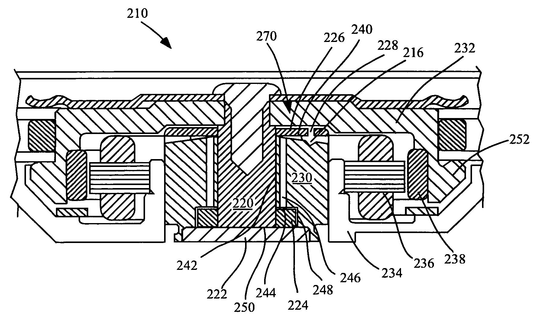
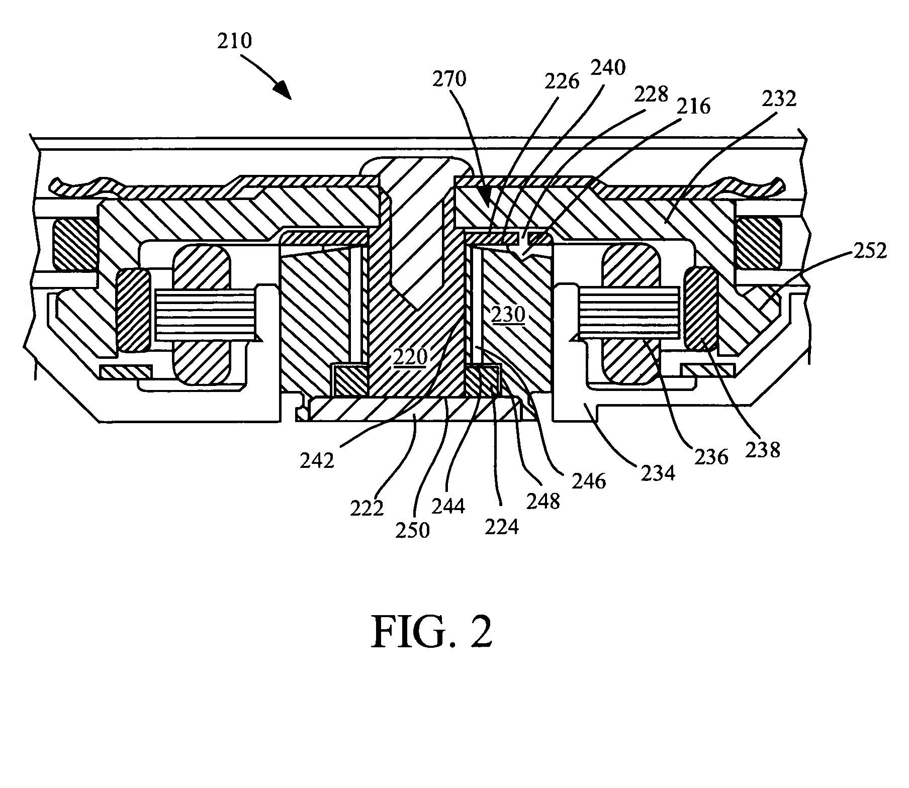
[0010]Improved capillary sealing is provided that withstands operating mode and non-operating mode mechanical shock, vibration and evaporation for use with fluid dynamic bearings, which in turn may be incorporated into a spindle motor or the like. In an embodiment, the sealing system withstands at least 1000 G shock. Also provided is a capillary seal system that occupies minimal axial space so that the axial length of a bearing may be maximized, optimizing bearing stiffness and performance. Further provided is a capillary seal system that may be utilized with a variety of bearing designs, including conical bearing designs. Additionally, the capillary seal provides a fluid reservoir that has a larger volume than a conventional capillary seal so that proper fluid volume is maintained within a fluid dynamic bearing. Further, the fluid reservoir allows for usage of lower viscosity oil, lowering power loss.
[0012]Strong fluid capillary force gradients surround the fluid fill pool, and weaker capillary force gradients exist in the fluid fill pool. A fluid meniscus forms an arch partially around the fluid fill pool. The fill pool, having a greater diverging angle than the reservoir provides an unstable region for fluid to remain. In the case of a shock event, fluid may become situated within the area of the fluid fill pool. Any fluid is pulled to the reservoir (a more stable region), directed away from the fill pool and consequently away from the fill / vent hole. The small fluid fill hole and an optional vent hole minimizes the surface area available for fluid leakage and evaporation. Should fluid arrive within the fluid fill pool after a shock event, it is promptly moved from the unstable region. In a subsequent shock event the fluid is not situated in line with the fluid fill / vent hole where it can be ejected through the hole.

Problems solved by technology

However, the demand for increased storage capacity and smaller disc drives has led to the read / write head being placed increasingly close to the disc surface.
A slight wobble or run-out in disc rotation can cause the disc to strike the read / write head, possibly damaging the disc drive and resulting in loss of data.
Imperfections in the raceways and ball bearing spheres result in vibrations.
Also, resistance to mechanical shock and vibration is poor in the case of ball bearings, because of low damping.
Vibrations and mechanical shock can result in misalignment between data tracks and the read / write transducer.
These shortcomings limit the data track density and overall performance of the disc drive system.
Because this rotational accuracy cannot be achieved using ball bearings, disc drives currently utilize a spindle motor having fluid dynamic bearings on the shaft and a thrust plate to support a hub and the disc for rotation.
Further, hydrodynamic bearings can be scaled to smaller sizes whereas ball bearings have smallness limitations.
However, hydrodynamic bearings suffer from sensitivity to external loads or mechanical shock events.
Fluid can in some cases be jarred out of the bearing by vibration or shock events.
Further, bearing fluid is susceptible to evaporation over time.
These particles can deposit on the read / write heads and the surfaces of the discs, causing damage to the discs and the read / write heads as they pass over the discs.
However, with a larger reservoir having diverging walls, the capillary seal gap is widened and thus the oil retention capability is lowered.
Moreover, although a radial capillary provides some shock resistance, its shock resistance is limited.
Tests show that recent radial capillary seal designs fail at about 500 Gs of shock, and fluid leaks through fill holes at about 500 Gs of shock.
Laptop or portable computers can be subjected to large magnitudes of mechanical shock as a result of handling.

Method used


Image

  • Capillary seal with fill pool
  • Capillary seal with fill pool
  • Capillary seal with fill pool

Examples


Embodiment Construction

[0022]Exemplary embodiments are described with reference to specific configurations. Those of ordinary skill in the art will appreciate that various changes and modifications can be made while remaining within the scope of the appended claims. Additionally, well-known elements, devices, components, methods and the like may not be set forth in detail in order to avoid obscuring the invention.

[0023]A system and method of capillary sealing that withstands at least 1000 G shock events, vibration and evaporation is described herein. It will be apparent that features of the discussion and claims may be utilized with disc drives, spindle motors, various fluid dynamic bearing designs including hydrodynamic and hydrostatic bearings, and other motors employing a stationary and a rotatable component.

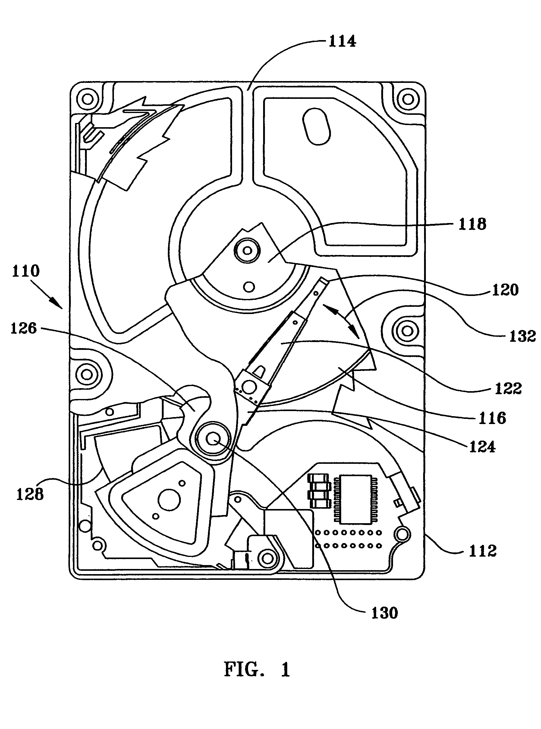
[0024]Referring to the drawings wherein identical reference numerals denote the same elements throughout the various views, FIG. 1 illustrates a typical disc drive data storage device 110 in which ...


PUM


Abstract

Improved capillary sealing is provided for withstanding shock events, vibration and evaporation, for use with fluid dynamic bearings. In an aspect, minimal axial space is occupied by a fluid reservoir and the sealing system and method withstands at least 1000 G shock events. A fluid reservoir having a capillary surface is formed between diverging walls. A fluid fill pool, separate from the fluid reservoir and having a steeper angle than the fluid reservoir, is positioned adjacent to a fluid fill hole. The fill pool, having a greater diverging angle than the fluid reservoir provides an unstable region for fluid to remain and any fluid is pulled by capillary force gradient to the fluid reservoir.

Description

CROSS REFERENCE TO RELATED APPLICATION[0001]This application is based on a provisional application Ser. No. 60 / 460,498, filed Apr. 4, 2003, titled Radial Capillary Seal With Anti-Shock Venting, and assigned to the Assignee of this application and incorporated herein by reference.FIELD OF THE INVENTION[0002]The invention relates generally to spindle motors, and more particularly to fluid dynamic bearing capillary seals that withstand shock events and evaporation.BACKGROUND OF THE INVENTION[0003]Disc drive memory systems are widely utilized throughout the world today in traditional computing environments and more recently in additional environments. These systems are used by computers and more recently by devices including digital cameras, digital video recorders, laser printers, photo copiers, jukeboxes, video games and personal music players. Consequently, the demands on disc drive memory systems has intensified because of increased performance demands and due to new environments fo...

Claims


Application Information

Patent Timeline
Patent Type & Authority Patents(United States)
IPC IPC(8): F16C33/74F16J15/40
CPCF16J15/40F16C33/74
Inventor GRANTZ, ALAN LYNDONPARSONEAULT, NORBERT STEVENWOLDEMAR, CHRIS MICHAELLEE, JAMES SIDNEY
Owner SEAGATE TECH LLC
Why Eureka
Eureka Blog
Learn More