

Apparatus for pole pieces
- Summary
- Abstract
- Description
- Claims
- Application Information
AI Technical Summary
Benefits of technology
Problems solved by technology
Method used
Image

Examples
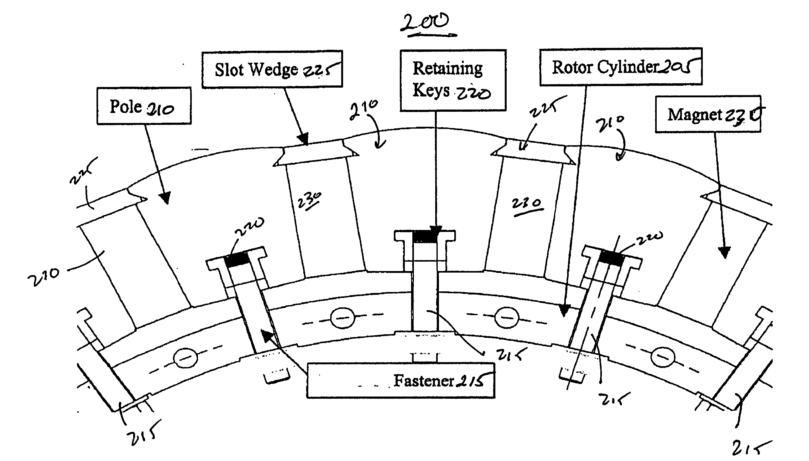
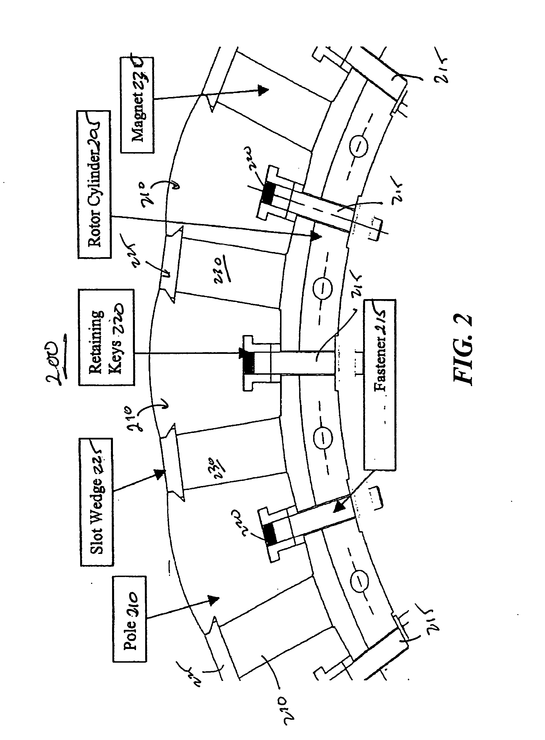
embodiment 200
[0031] As shown in FIG. 2, the embodiment 200 includes a rotor cylinder 205, multiple pole pieces 210, multiple fasteners 215, multiple retaining keys 220, multiple slot wedges 225, and multiple magnets 230.
[0032] The rotor cylinder 205 may be configured to be a substantially circular structure. The rotor cylinder 205 may be composed of a metallic material, for example aluminum, or a non-metallic material, for example ceramic, plastic or a reinforced composite material. The rotor cylinder 205 may be constructed as a solid piece or structural fabrication with a hollow center in order to reduce weight. In one embodiment, the rotor cylinder may include apertures or openings. The apertures may be precisely machined to center beneath a pole piece, thereby providing a method of precisely locating the pole pieces in a permanent magnet motor. The number of apertures per pole piece is a function of the length of the pole piece, diameter of attachment, diameter of the aperture and rotational ...
embodiment 300
[0041]FIG. 3 illustrates another embodiment 300 utilizing square bars and fasteners. It should be readily apparent to those of ordinary skill in the art that the embodiment 300 depicted in FIG. 3 represents a generalized schematic illustration and that other components may be added or existing components may be removed or modified.
[0042] As shown in FIG. 3, embodiment 300 includes rotor cylinder 305, multiple pole pieces 310, multiple fasteners 315, multiple slot wedges 325, multiple magnets 330, and multiple square bars 335. The rotor cylinder 305, pole pieces 310, slot wedges 325, and magnets 330 are similar to the comparable components shown with respect to embodiment 200 (shown in FIG. 2). Instead of retaining keys to engage the fastener member 315, embodiment 300 may include a square bar member 335. The horizontal opening of the pole pieces 310 may be adapted to receive the square bar member 335. More particularly, the fasteners are drilled through from the inside diameter to t...
embodiment 400
[0045] In embodiment 400, the pole pieces 410 are stacked and welded on the edges to form a single solid polyhedron which is attached the rotor cylinder 405 by engaging the fastener member 415 through the respective aperture of the rotor cylinder 405 and vertical opening of the pole piece 410. After the pole pieces 410 are attached to the rotor cylinder 405, the magnets 430 are placed in the gap formed by two pole pieces 410 and slot wedges 425 may then be inserted to form the housing to hold the magnet 430 secure against the rotor cylinder 405.
[0046]FIG. 5 illustrates an exemplary embodiment 500 utilizing welded poles, bars and fasteners. It should be readily apparent to those of ordinary skill in the art that the embodiment 500 depicted in FIG. 5 represents a generalized schematic illustration and that other components may be added or existing components may be removed or modified.
[0047] As shown in FIG. 5, embodiment 500 includes a rotor cylinder 505, multiple pole pieces 510, m...
PUM
 Abstract
Description
Claims
Application Information