
Pushbutton controlled correction tape assembly

a technology of correction tape and pushbutton, which is applied in the direction of erasing devices, printing, thin material processing, etc., can solve the problems of easy polluting of the correction tape assembly again and easy stained white coating on the paper belt, and achieve the effect of easy application of the correction tap

Inactive Publication Date: 2006-11-16
SDI CORPORATION
View PDF2 Cites 45 Cited by
  • Summary
  • Abstract
  • Description
  • Claims
  • Application Information

AI Technical Summary

Benefits of technology

[0007] The primary objective of the present invention is to provide a pushbutton assembly to control the extension of the correction tape so that the user is able to easily apply the correction tape as required.
[0008] Another objective of the present invention is that the correction tape assembly has an application head through which the correction tape runs over. The application head is pivotable relative to the correction tape assembly so that the user is able to easily apply the correction tape to wherever required.
[0009] In still another objective of the present invention, the correction tape assembly has a pushbutton assembly mounted inside the correction tape assembly to control extension of the application head so that the correction tape is protected from pollution when the correction tape is not in use.

Problems solved by technology

However, the white coating on the paper belt is easily stained such that often the user will have to skid over a portion of the correction tape (to reel back in the casing a portion of the correction tape) for application of a clean coating.
When the cover is lost, the correction tape assembly again is easily polluted.

Method used


Image

  • Pushbutton controlled correction tape assembly
  • Pushbutton controlled correction tape assembly
  • Pushbutton controlled correction tape assembly

Examples


Embodiment Construction

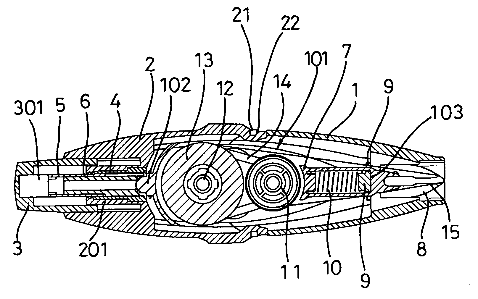
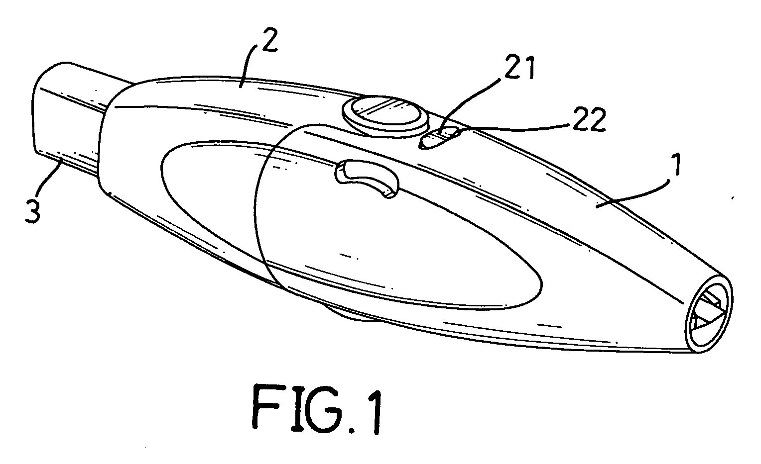
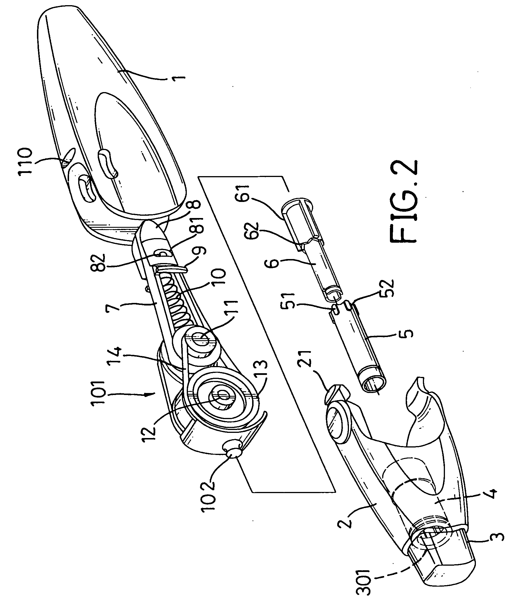
[0027] With reference to FIGS. 1 and 2, it is noted that the correction tape assembly in accordance with the present invention includes a casing composed of a front cover (1) and a rear cover (2) detachably connected to the front cover (1) to define therebetween a receiving space (not numbered), a pushbutton (3) movably received in the rear cover (2), a pushbutton assembly received in the casing and composed of a driven tube (4), a rotation tube (5) and a control tube (6), a bracket (7) through which a correction tape runs and an application head (8) mounted at a front of the bracket (7).

[0028] The front cover (1) has a clamping recess (110) defined in a front face thereof and the rear cover (2) has a ledge with a hook (21) extending out from a side face thereof to correspond to the clamping recess (110) of the front cover (1) so that the front cover (1) and the rear cover (2) are detachably connected to each other to form a casing so as to receive therein the driven tube (4), the ...


PUM


Abstract

A pushbutton controlled correction tape assembly includes a casing having therein a correction tape assembly having an application head, a pushbutton assembly received in the casing to selectively extend the application head of the correction tape assembly out of the casing so as to apply a correction tape to a surface.

Description

BACKGROUND OF THE INVENTION [0001] 1. Field of the Invention [0002] The present invention relates to a correction tape assembly, and more particularly to a correction tape which is controlled by a pushbutton assembly. [0003] 2. Description of Related Art [0004] Correction tapes are extensively used in writing and typing whenever there is an error. The user places the correction tape on top of the place where the error is and then presses and moves the correction tape to allow the correction tape to adhere to the surface to cover the error. Thereafter, the user is able to write / type on the corrected portion. The introduction of such correction tape simplifies correcting paperwork because the user no longer needs to retype or rewrite the entire article just for a small mistake. [0005] The mostly commonly known correction tape assembly has a casing and a reel rotatably received in the casing. When the correction tape assembly is employed on a surface, the coating on a paper belt is adh...

Claims


Application Information

Patent Timeline
IPC IPC(8): B43L19/00
CPCB65H37/007
Inventor CHEN, JAU-SHYONG
Owner SDI CORPORATION
Learn More