Virtual wall system

Inactive Publication Date: 2006-11-16
INFINITE ELECTRONICS
View PDF3 Cites 117 Cited by
  • Summary
  • Abstract
  • Description
  • Claims
  • Application Information

AI Technical Summary

Benefits of technology

[0007] The secondary objective of the present invention is to provide

Problems solved by technology

However, while operated, the light transmitting unit must keep emitting the light beam to ensure the light receiving unit to receive the light beam while the mobile robotic vacuum cleaner passes by it, thus keeping consuming the power energy.
If the power energy of the light transmitting unit is supplied by the battery,

Method used


Image

  • Virtual wall system
  • Virtual wall system
  • Virtual wall system

Examples


Embodiment Construction

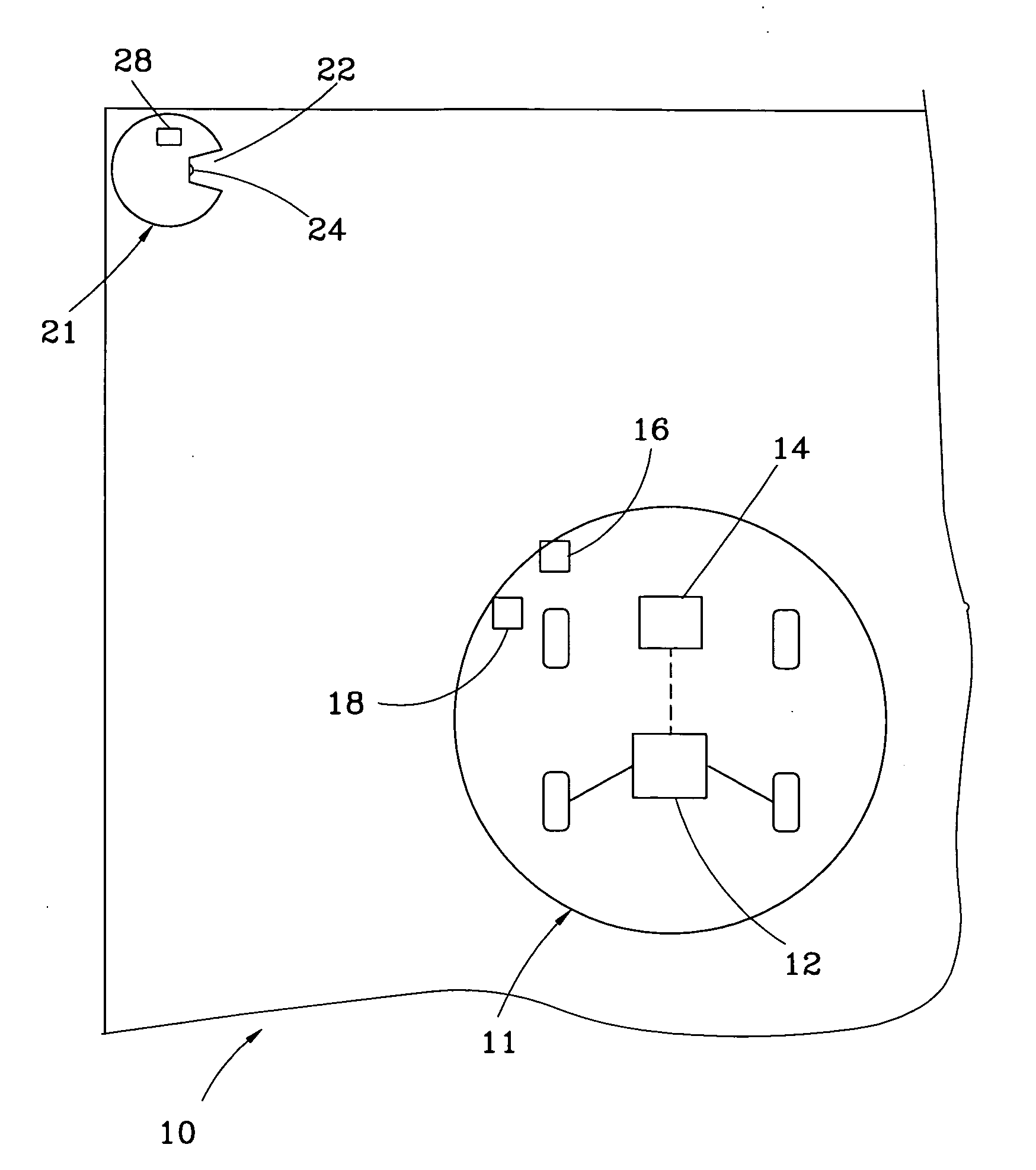
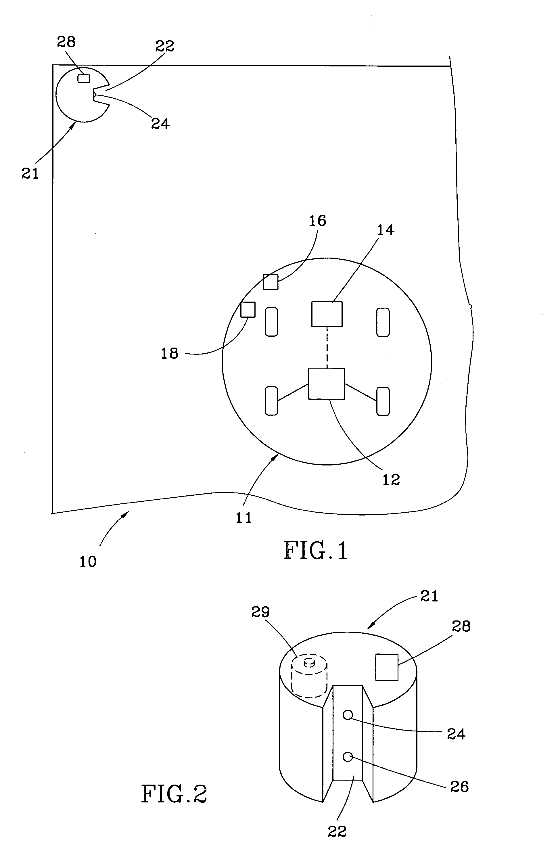
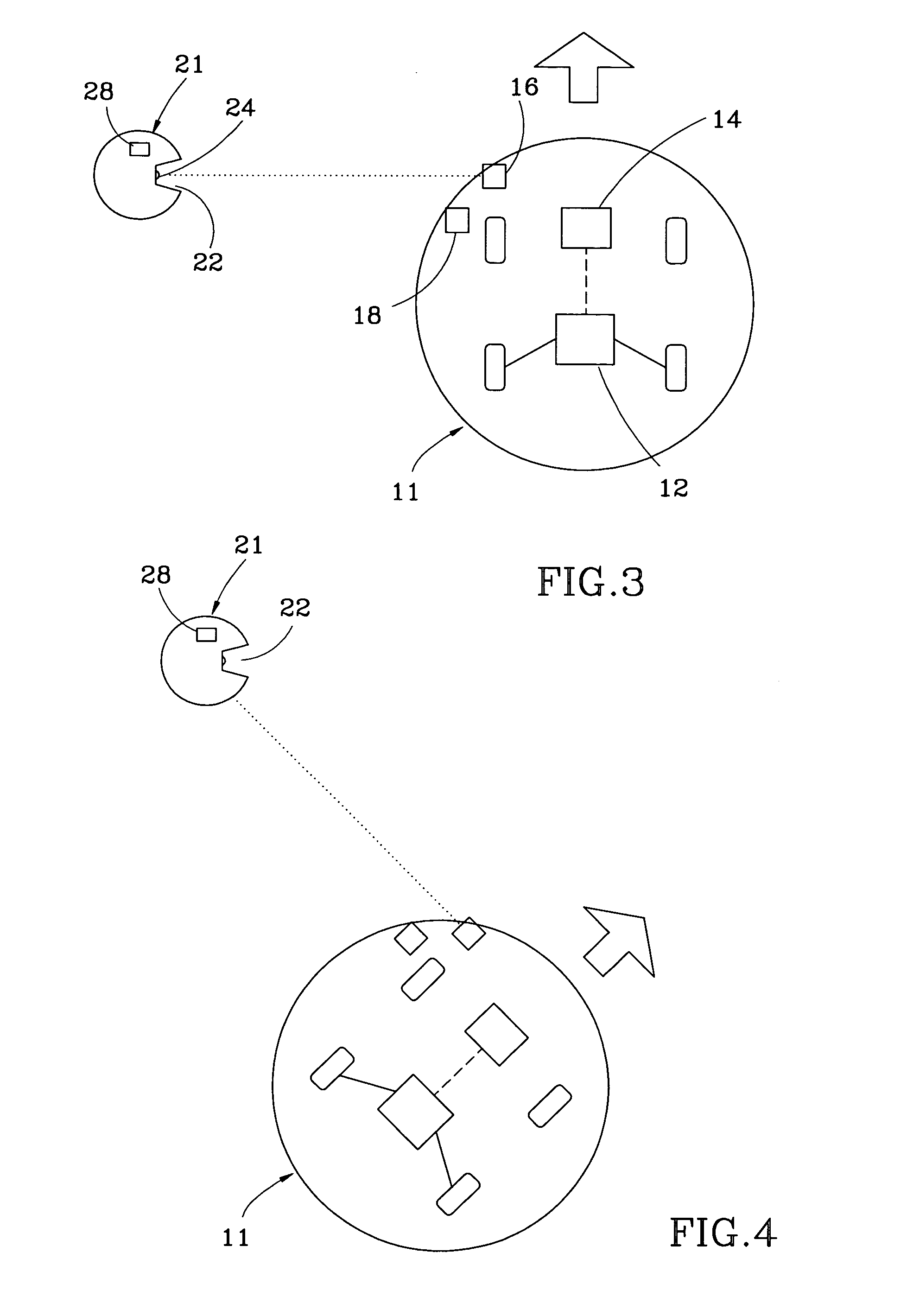
[0016] Referring to FIGS. 1 and 2, a virtual wall system 10 for control of a mobile robotic device is composed of a mobile robotic device 11 and a virtual wall system 21.

[0017] The mobile robotic device 11 includes a steering unit 12 for steering itself toward at least one direction, a steering control unit 14 connected with the steering unit 12 for controlling the steering of the steering unit 12, at least one signal transmitter 16 mounted on a side thereof for emitting a (light) signal towards a direction against the mobile robotic device 11, and a sonic receiver 18 provided for receiving a sonic signal.

[0018] The virtual wall generator 21 is mounted on a planar surface that the mobile robotic device 11 moves, like the ground, including at least one cavity 22, a signal receiver 24, a sonic transmitter 26, a signal controller 28, and a power module 29. The cavity 22 is taper-shaped to be defined between two sloped sidewalls and a bottom sidewall, having an opening facing sideward...


PUM


Abstract

A virtual wall system includes a mobile robotic device having a steering unit for steering itself, a steering control unit connected with the steering unit for controlling the steering of the steering unit, at least one signal transmitter mounted thereon for emitting a signal, and a sonic receiver for receiving a sonic signal; and a virtual wall generator having at least one signal receiver for receiving the signal, at least one sonic transmitter for emitting a sonic signal, and a signal controller for identifying the signal and controlling the emission of the sonic transmitter. While the mobile robotic device is moving, the signal controller controls the sonic transmitter to emit the sonic signal after the signal receiver receives the signal emitted by the signal transmitter and then the sonic receiver receives the sonic signal, enabling the steering control unit to control the steering unit to steer the mobile robotic device.

Description

BACKGROUND OF THE INVENTION [0001] 1. Field of the Invention [0002] The present invention relates generally to control of a mobile robotic device, and more particularly, to a virtual wall system. [0003] 2. Description of the Related Art [0004] A conventional mobile robotic device, like a mobile robot, a mobile carrier, or a mobile robotic vacuum cleaner, is based on a predetermined path or visual recognition for identification of the direction, speed, and distance of movement. For example, as disclosed in U.S. Patent Publication No. 2004 / 0,111,184, a mobile robotic vacuum cleaner enables a light beam to function as a virtual wall by its light transmitting unit thereof mounted on a predetermined position for emitting the light beam toward a predetermined direction and its light receiving unit provided for receiving the light beam. While moving to receive the light beam, the mobile robotic vacuum cleaner emits a signal of diversion to keep itself within a working area defined by the l...

Claims


Application Information

Patent Timeline
IPC IPC(8): G06F19/00
CPCG01S1/725G05D2201/0215G05D1/0255
Inventor CHIU, TING-YIN
Owner INFINITE ELECTRONICS
Why Eureka
Try Eureka