
System and method for flight plan data capture

a flight plan and data capture technology, applied in the field of system and method for flight plan data capture, to achieve the effect of facilitating the proposal

Active Publication Date: 2006-11-16
RLM SOFTWARE
View PDF21 Cites 53 Cited by
  • Summary
  • Abstract
  • Description
  • Claims
  • Application Information

AI Technical Summary

Benefits of technology

The invention provides a way for users to get ranked based on their likelihood of getting permission to travel to different destinations. This helps them suggest routes more easily because they know which ones are most likely to receive approval first.

Problems solved by technology

The technical problem addressed by this patent is how to securely receive and utilize flight plan information submitted through the internet by pilots, while ensuring that the flight plan can still be modified based on real-time circumstances like air travel demand and weather patterns.

Method used


Image

  • System and method for flight plan data capture
  • System and method for flight plan data capture
  • System and method for flight plan data capture

Examples


Embodiment Construction

[0042] Definitions. As used in this description and the accompanying claims, the following terms shall have the meanings indicated, unless the context otherwise requires:

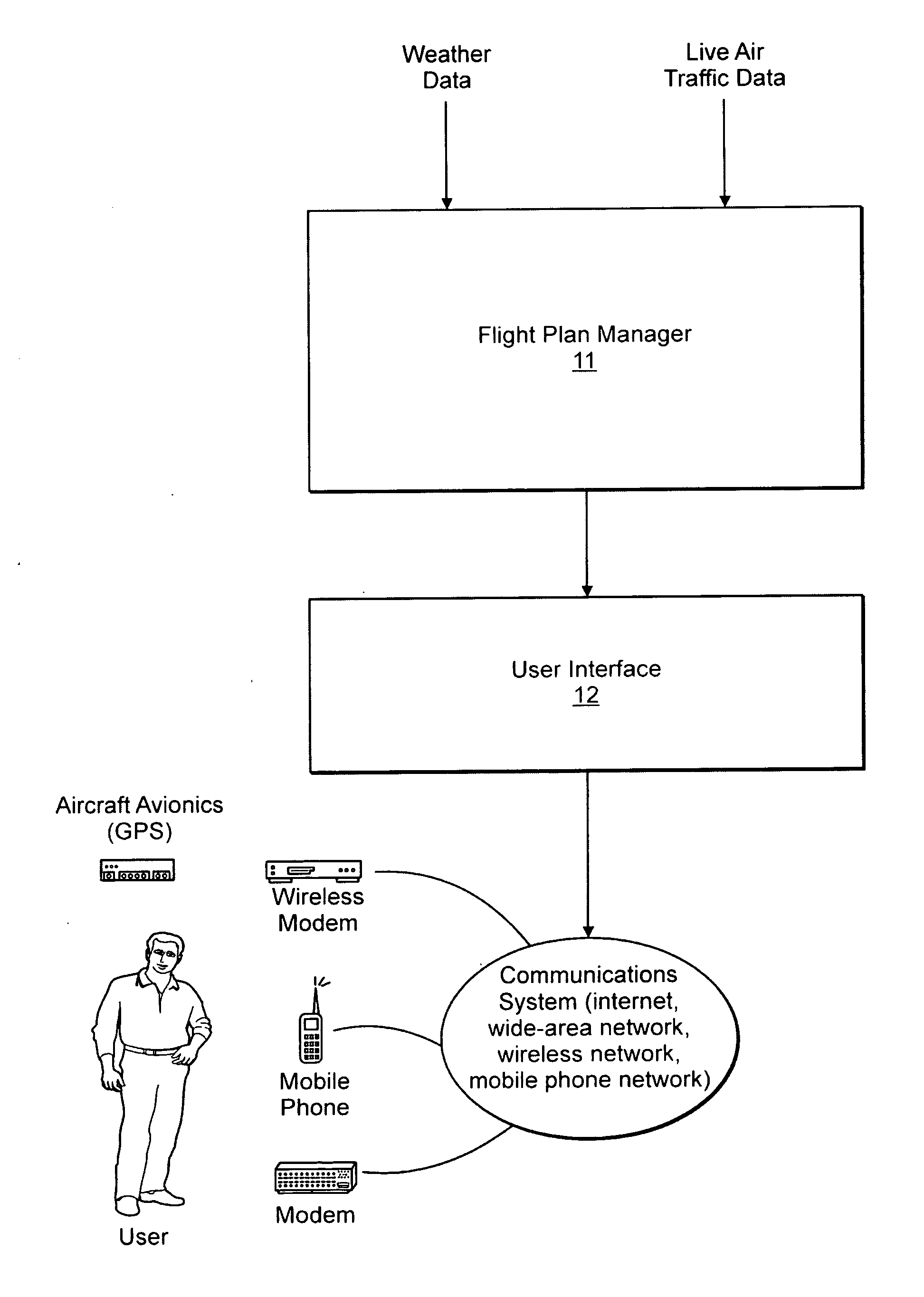
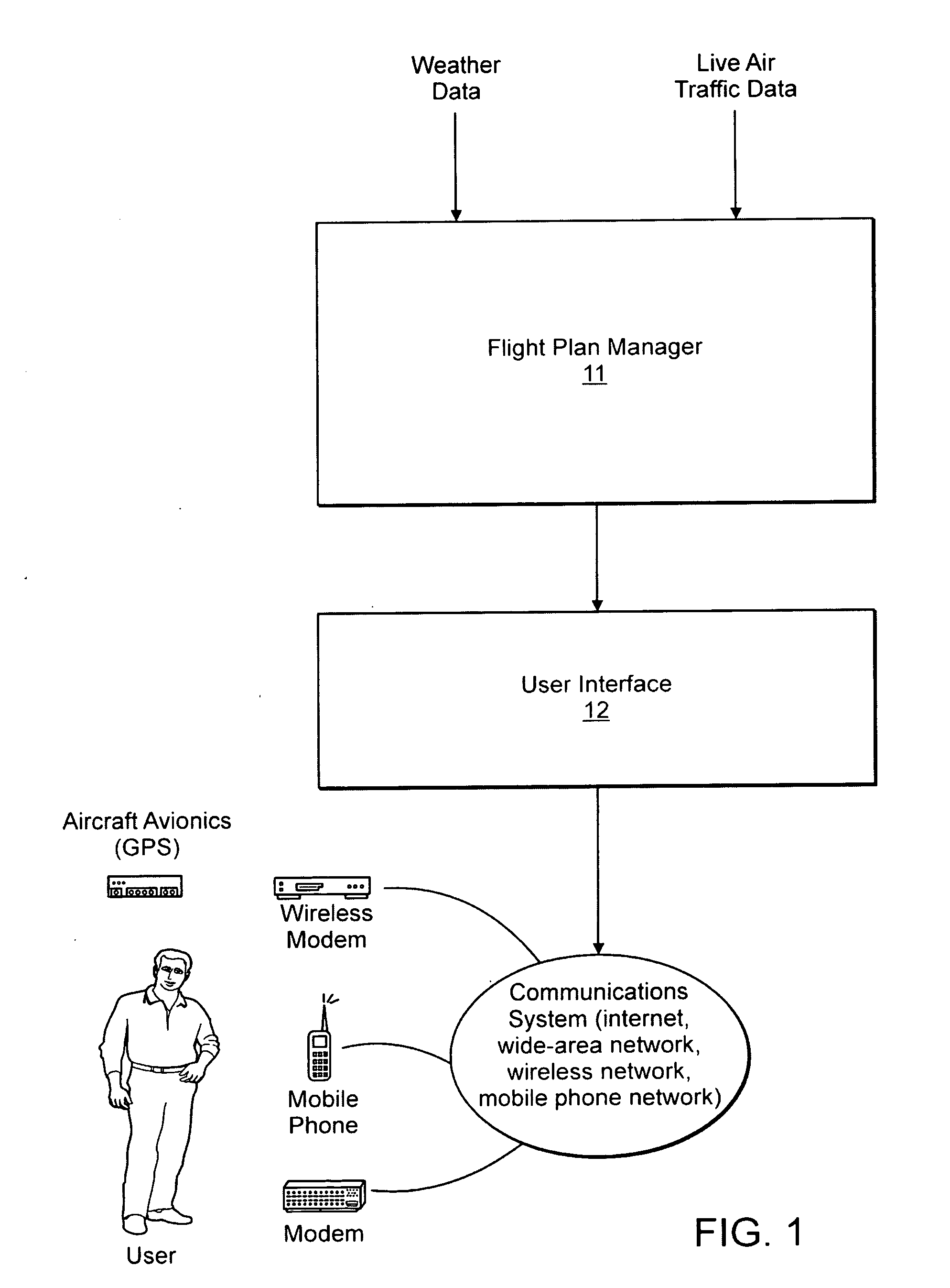
[0043]FIG. 1 is a block diagram providing an overview of data flow in accordance with a preferred embodiment of a method in accordance with the present invention. In this embodiment it can be seen from the diagram that providing a candidate list of flight plan data, to a user, for an air trip of interest depends upon receiving live air traffic data, and optionally weather data, processing and managing that data in accordance with the Flight Plan Manager 11, and providing the abstracted flight plan data to a user via interface 12.

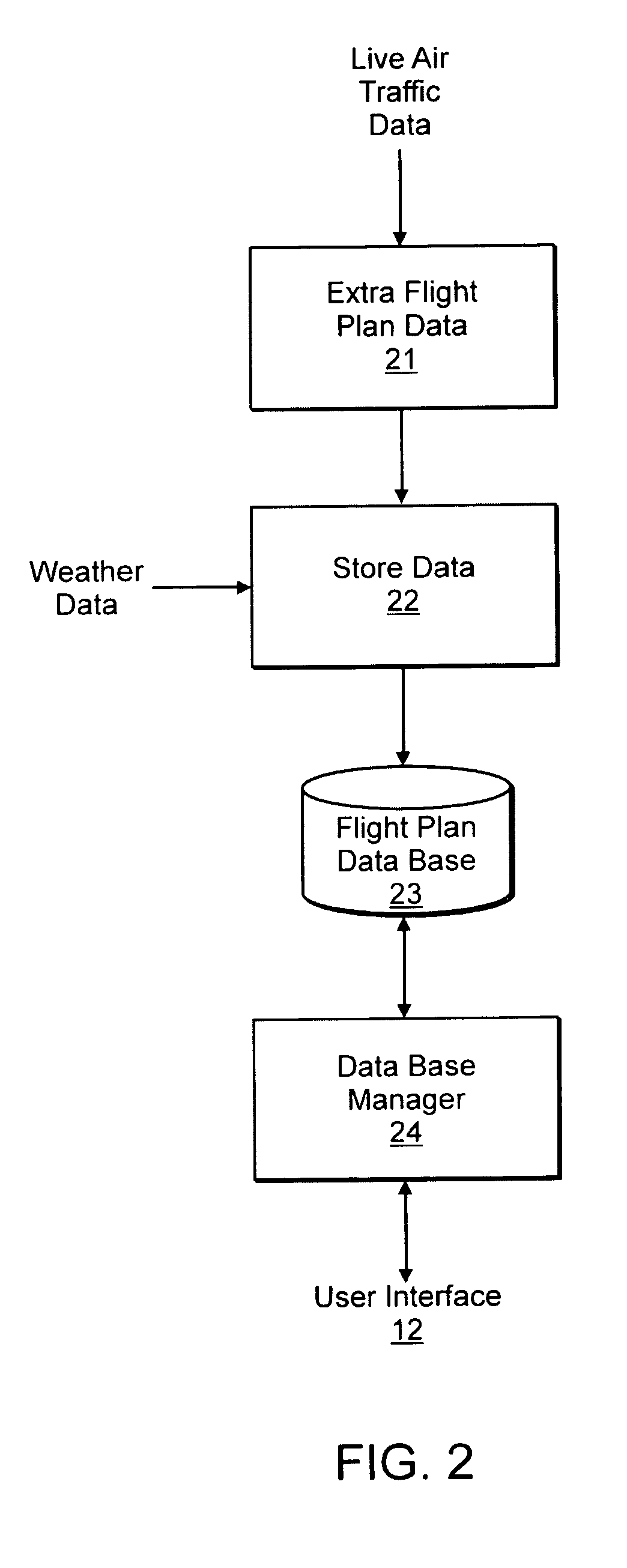
[0044]FIG. 2 is a block diagram showing further detail of the Flight Plan Manager (FPM) 11 of FIG. 1. It can be seen that in accordance with process 21 the flight plan data is extracted from live air traffic data. The live air traffic data can be received from an aviation authority or avia...


PUM


Abstract

A system and method for providing to a user a candidate list of flight plans that specify one or more planned routes of flight from one location to another location, such routes satisfying certain criteria. These criteria include ranking the candidate list of flight plans according to the probability that the flight plan may be allowed or cleared by a controlling authority based on historic cleared flight plans; further qualifying this list by considering only candidate flight plans cleared during specified weather conditions; or specified time periods; or requested speed and/or altitude and/or aircraft type of flight parameters. Various embodiments include providing the candidate list of flight plans to the user by means of a communication system that is composed of a combination of a wide-area network, a wireless network or the internet. Additionally, an embodiment includes providing the flight plan data to a global positioning system (GPS) of a user.

Description


Claims


Application Information

Patent Timeline
Owner RLM SOFTWARE
Learn More