Off-axis rotary joint

Inactive Publication Date: 2006-11-23
FOCAL TECH
View PDF1 Cites 45 Cited by
  • Summary
  • Abstract
  • Description
  • Claims
  • Application Information

AI Technical Summary

Benefits of technology

[0018] The signal may pass through one, but not the other, of the conductors. Alternati

Problems solved by technology

All display high optical losses that require active regeneration of signals, and are impractical for a multiplicity of singlemode optical fibers.
These are not suited to the

Method used


Image

  • Off-axis rotary joint
  • Off-axis rotary joint
  • Off-axis rotary joint

Examples


Embodiment Construction

[0028] At the outset, it should be clearly understood that like reference numerals are intended to identify the same structural elements, portions or surfaces consistently throughout the several drawing figures, as such elements, portions or surfaces may be further described or explained by the entire written specification, of which this detailed description is an integral part. Unless otherwise indicated, the drawings are intended to be read (e.g., cross-hatching, arrangement of parts, proportion, degree, etc.) together with the specification, and are to be considered a portion of the entire written description of this invention. As used in the following description, the terms “horizontal”, “vertical”, “left”, “right”, “up” and “down”, as well as adjectival and adverbial derivatives thereof (e.g., “horizontally”, “rightwardly”, “upwardly”, etc.), simply refer to the orientation of the illustrated structure as the particular drawing figure faces the reader. Similarly, the terms “inw...


PUM


Abstract

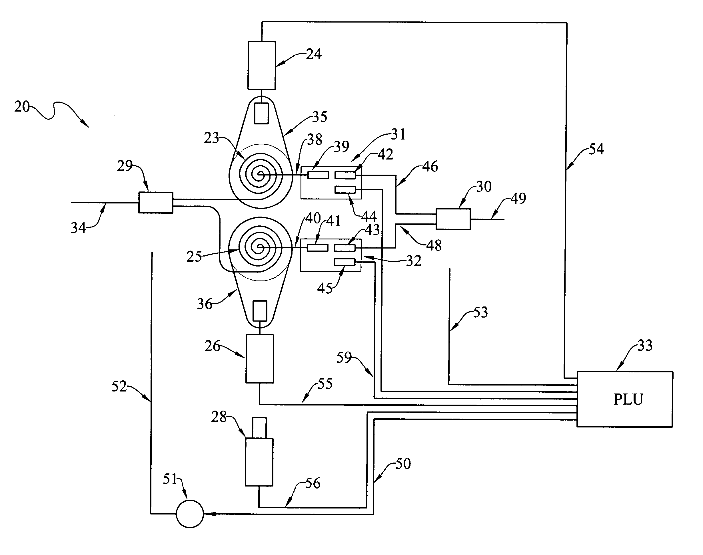
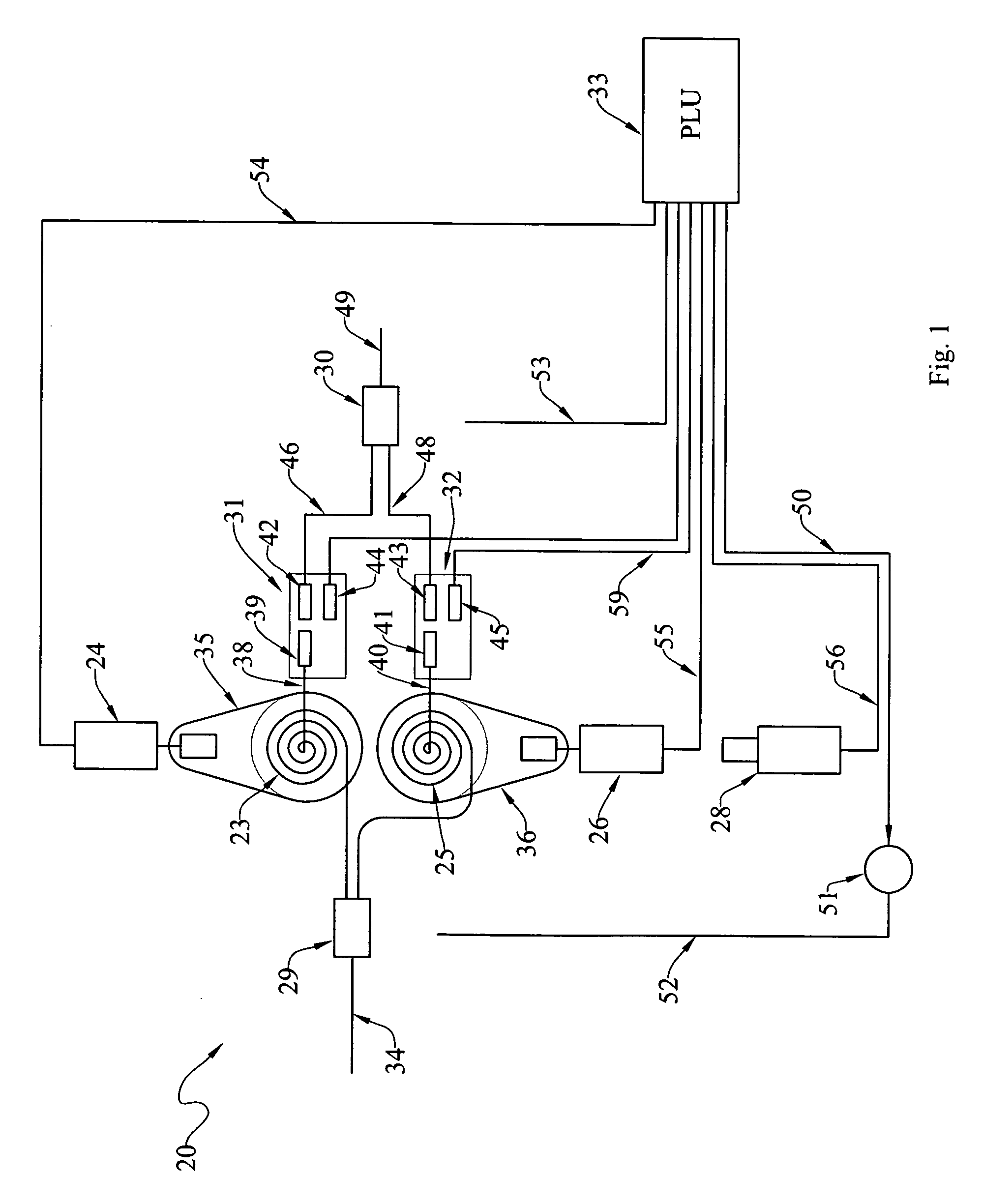
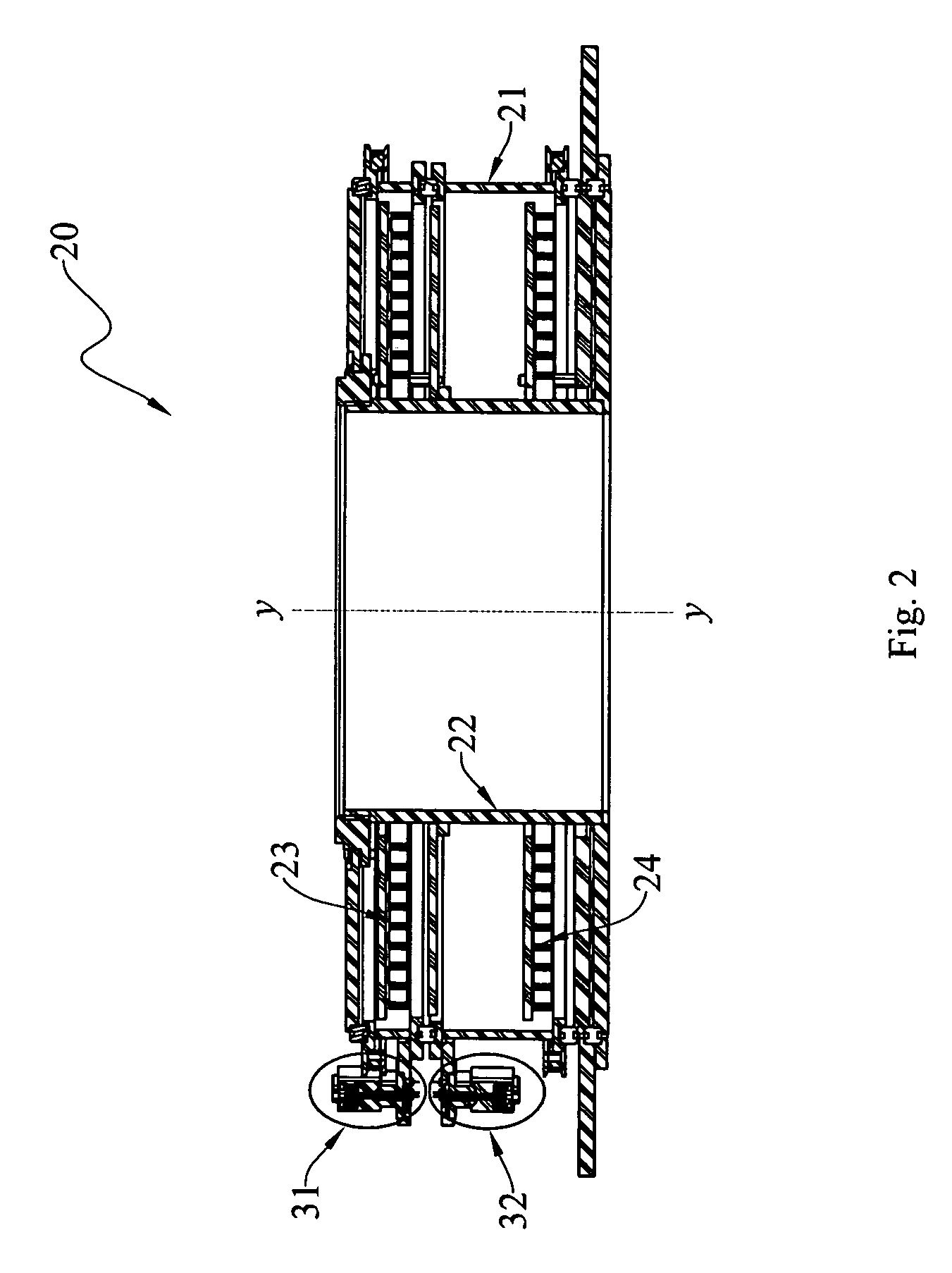
An off-axis rotary joint (20) for selectively enabling communication of a signal (i.e., electrical and/or optical) between a housing (21) mounted for rotation about an axis (y-y) relative to a hollow shaft assembly (22) at all permissible relative angular displacements (e.g., 0°, 180°, 360°, 540°, 720°, etc.) between the housing and shaft assembly, broadly includes: a first conductor (23) having an first end mounted on the second member and having a second end mounted on the first member, the first conductor being adapted to convey a signal between its ends; a first motor (24) operatively arranged to selectively rotate the first conductor first end through a desired angular displacement relative to the second member; a second conductor (25) having an first end mounted on the second member and having a second end mounted on the first member, the second conductor being adapted to convey a signal between its ends; a second motor (26) operatively arranged to selectively rotate the second conductor second end through a desired angular displacement relative to the first second member; an encoder (28) for monitoring the angular displacement of the first member relative to the second member; a first divider/combiner (29) communicating with the second end of each of the conductors; a second divider/combiner (30); a first connector (31) mounted on the first member for selectively communicating the first and second divider/combiners through the first conductor; a second connector (32) mounted on the first member for selectively communicating the first and second divider/combiners through the second conductor; and a controller (33) for selectively operating the first and second motors and the first and second connectors; whereby a signal may be conveyed though the joint at all permissible angular displacements of the housing relative to the shaft assembly.

Description

CROSS-REFERENCE TO RELATED APPLICATION [0001] This application claims the benefit of the earlier filing date of provisional U.S. Pat. Application Ser. No. 60 / 675,335, filed on Apr. 27, 2005.TECHNICAL FIELD [0002] The present invention relates generally to the field of off-axis rotary joints, and, more particularly, to improved off-axis rotary joints that enable communication of a signal between a housing mounted for rotation about an axis relative to a shaft assembly at all permissible relative angular displacements between the housing and shaft assembly. BACKGROUND ART [0003] The use of fiber optic transmission techniques is now well accepted in telephone and data transmission arts. Optical multiplexing to enable each fiber to carry a great multitude of data and voice channels is also well understood. Several applications require the passage of power or communication signals (e.g., voice, video, data streams, etc.) across an interface between a rotating reference frame and a non-ro...

Claims


Application Information

Patent Timeline
IPC IPC(8): H02B7/06
CPCH04B10/22G02B6/3604H04B10/801
Inventor MCKAY, ROBERT FISHER
Owner FOCAL TECH
Why Eureka
Try Eureka