Automatically adjusting passenger reading light system and method

Active Publication Date: 2006-11-23
THE BOEING CO
View PDF4 Cites 45 Cited by
  • Summary
  • Abstract
  • Description
  • Claims
  • Application Information

AI Technical Summary

Benefits of technology

[0009] The various preferred embodiments enable automatic re-aiming of the light beam from the light assembly without any manual adjustment or intervention by the occupant seated in the s

Problems solved by technology

Such lights are typically of a relatively complex constr

Method used


Image

  • Automatically adjusting passenger reading light system and method
  • Automatically adjusting passenger reading light system and method
  • Automatically adjusting passenger reading light system and method

Examples


Embodiment Construction

[0018] The following description of the preferred embodiment(s) is merely exemplary in nature and is in no way intended to limit the invention, its application, or uses.

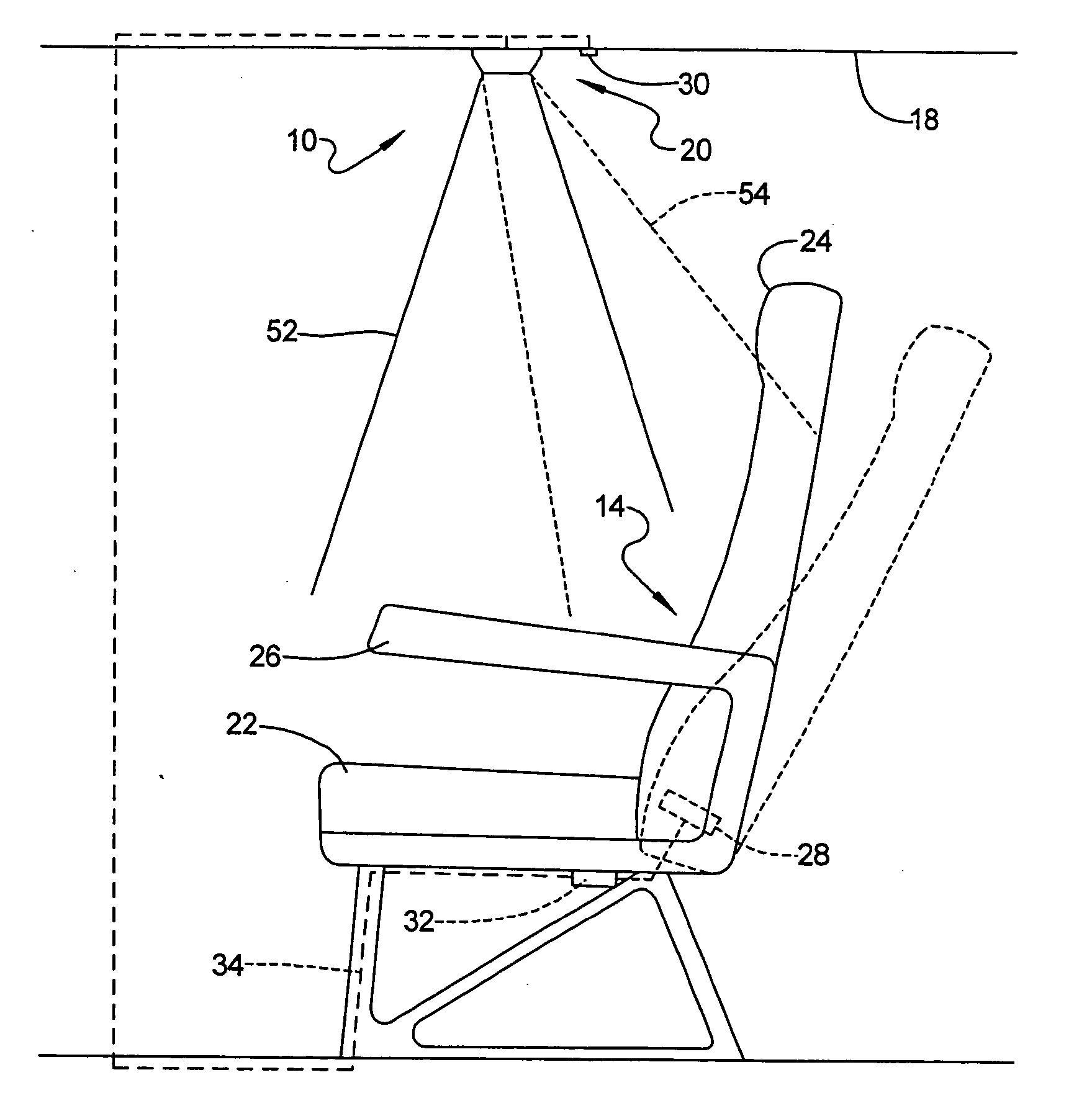
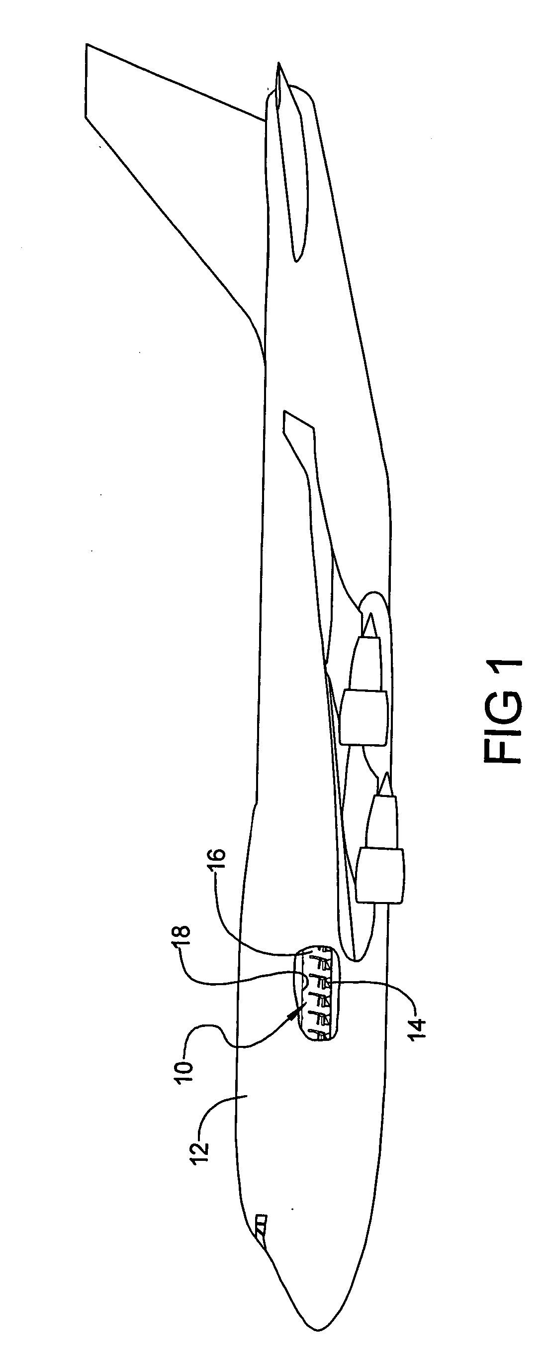
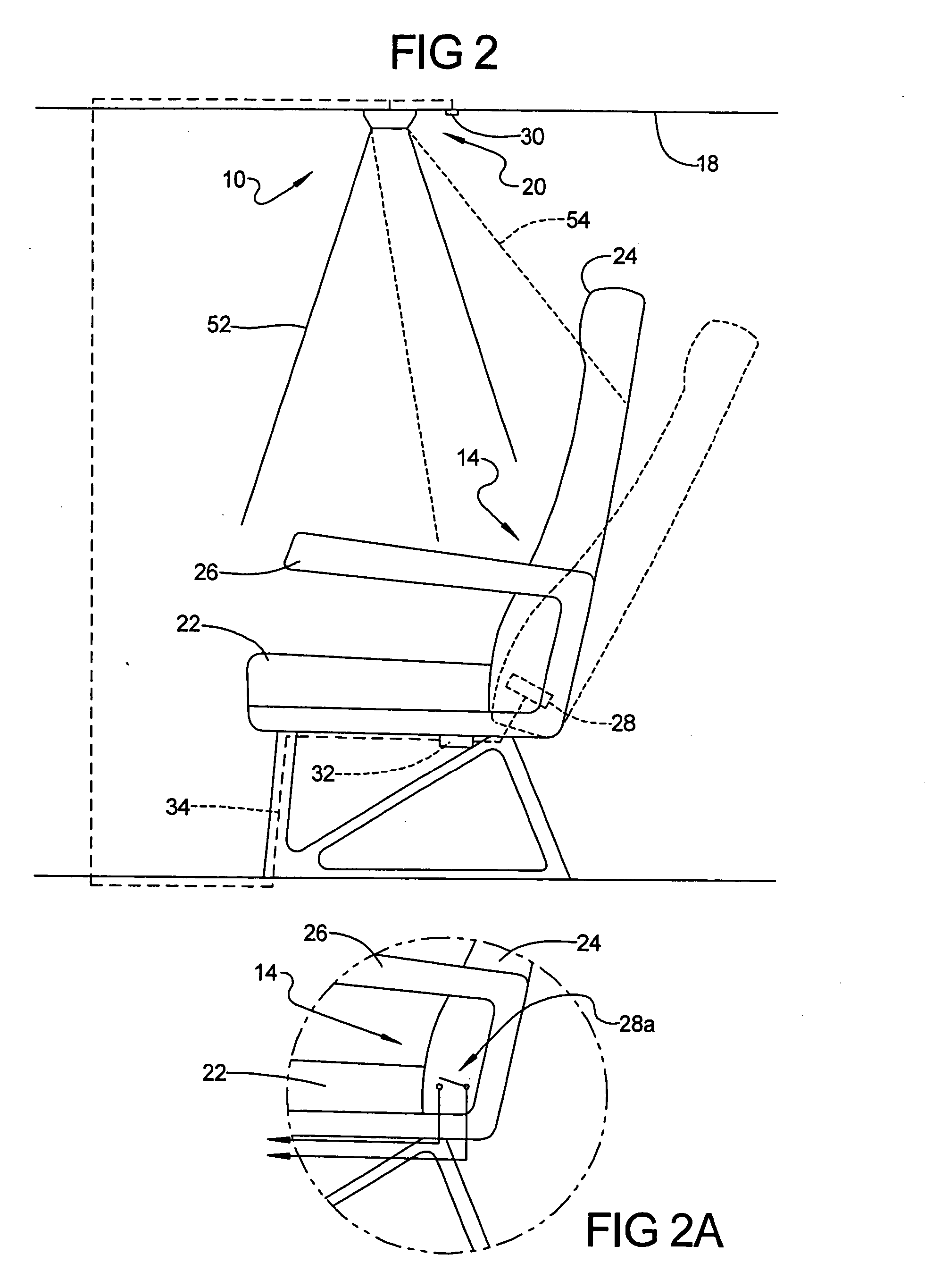
[0019] Referring to FIG. 1, there is shown a light system 10 in accordance with a preferred embodiment of the present invention implemented on a mobile platform. In this example, the mobile platform is a commercial aircraft 12. The light system 10 is used in connection with a given seat 14 in a cabin area 16 of the mobile platform 12. A separate light system 10 is used in connection with each seat 14. The light system 10 includes a light assembly that will be described and shown in greater detail in FIGS. 2 and 3, which is supported from an overhead wall portion 18 in the cabin area 16. Thus, each seat 14 has an independent one of the systems 10 associated with it. While a commercial aircraft 12 has been shown in FIG. 1, it will be appreciated that the light system 10 can be implemented in virtually any form of mobi...


PUM


Abstract

A lighting system and method for producing an automatically positionable light beam that is aimed in accordance with the position of a seatback portion of a seat on a mobile platform. The system includes a light assembly having independent first and second light subsystems, with each light subsystem having a plurality of LEDs or incandescent bulbs. A switch mounted on the seat detects when the seatback portion of the seat is in an upright or a reclined position, and provides a signal to the light assembly in accordance with the position of the seatback. The signal is used to turn on either the first light subsystem to illuminate a lap area of the occupant when the seat is in its upright position, or the second light subsystem to illuminate an area slightly rearwardly of the occupant's lap when the seat is in the reclined position. Thus, optimum positioning of the light beam produced by the light assembly is achieved automatically, without requiring any manual adjustment by the seat occupant.

Description

FIELD OF THE INVENTION [0001] The present invention relates to lighting systems, and more particularly to a lighting system adapted for use on a mobile platform in which the light beam projected by the light system is automatically aimed at different areas of the seat in response to the position of a seatback portion of the seat. BACKGROUND OF THE INVENTION [0002] Various forms of mobile platforms, and particularly commercial aircraft, typically employ a reading light positioned in an overhead area over each seat on the mobile platform. Typically, these lights have been manually adjustable by the seat occupant. Such lights are typically of a relatively complex construction that employs an orbitally supported light element. The housing of the light element may be grasped and manually positioned by the seat occupant so that it illuminates a first area over the seat when the occupant is seated in an upright position in the seat, and a second area that is slightly rearward of the first ...

Claims


Application Information

Patent Timeline
IPC IPC(8): G08B21/00
CPCB60Q3/0259B60Q3/0293Y10S362/802B64D2011/0053Y02T50/46B64D11/00B60Q3/233B60Q3/47B60Q3/80Y02T50/40
Inventor COLACECCHI, JAY W.
Owner THE BOEING CO
Why Eureka
Try Eureka