Biopsy gun

A biopsy gun and casing technology, applied in the field of biopsy guns, can solve problems such as difficulty in preloading the biopsy gun

Inactive Publication Date: 2019-08-16
彼得普弗比尔股份有限公司
View PDF0 Cites 0 Cited by
  • Summary
  • Abstract
  • Description
  • Claims
  • Application Information

AI Technical Summary

Problems solved by technology

This leads to a minimum length of the entire biopsy gun, which makes it difficult to conveniently preload the biopsy gun with one hand

Method used


Image

  • Biopsy gun
  • Biopsy gun
  • Biopsy gun

Examples


Embodiment Construction

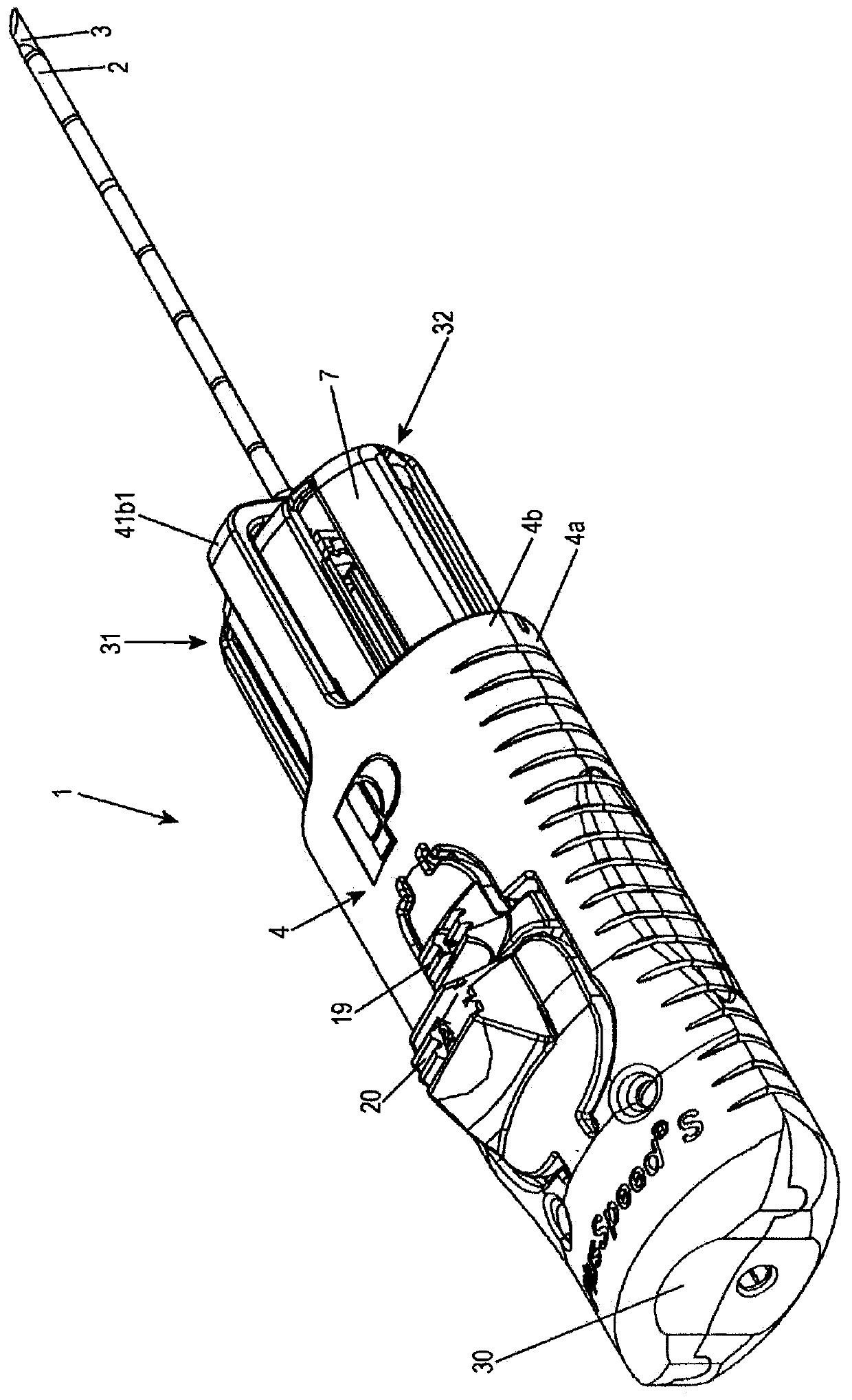
[0027] figure 1 A biopsy gun 1 is shown with a housing 4 , a clamping handle 7 , a cannula 2 and a needle tip 3 . Cannula 2 and needle tip 3 can be pretensioned separately by actuating clamping handle 7 twice. The user's index finger and middle finger can approach the clamping handle 7 through the two openings 31, 32 of the housing 4, while the user's thumb rests on the other end of the housing 4 in a non-slip manner in the recess 30 provided for it. middle. The housing 4 essentially comprises two half-shells 4 a , 4 b and the L-shaped frame elements 4 a 1 , 4 b 1 of the two half-shells 4 a , 4 b are respectively located between the openings 31 , 32 of the housing 4 . also, figure 1 A first button 19 for releasing the needle tip and a second button 20 for releasing the cannula are shown.

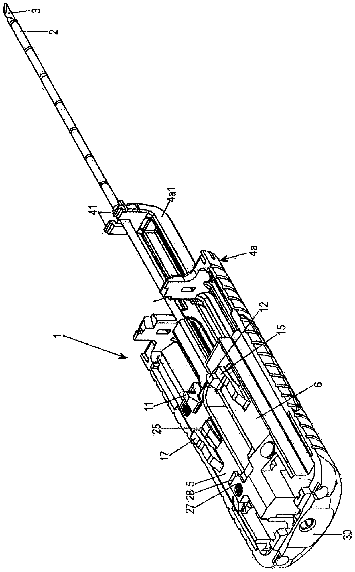
[0028] FIG. 2 shows the biopsy gun 1 without the clamping handle 7 and without the upper housing half-shell 4b. The biopsy gun 1 also has: a cannula slide 5 connected to the cannula 2 ;...


PUM


Abstract

The invention relates to a biopsy gun (1) comprising a cannula (2) and a stylet (3) which is guided in said cannula (2), and having the following: a housing (4), a cannula carriage (5) for moving thecannula (2), a stylet carriage (6) for moving the stylet (3), a tensioning handle (7) for tensioning the cannula carriage (5) and the stylet carriage (6) from a starting position into a tensioned position, and an engagement element (8) which is provided on said tensioning handle (7) and has depressions (9, 10) which can enter into engagement with corresponding projections (11, 12) of said cannulacarriage (5) and stylet carriage (6). The engagement element (8) is mounted on the tensioning handle (7) such that it can rotate, and is pretensioned by means of a spring (13) against a contact surface (14) of the housing (4).

Description

Background technique [0001] Manually clampable biopsy guns are known from the prior art, in which a cannula and a needle tip guided in the cannula can be clamped by means of two successive strokes of a clamping handle. For this purpose, the cannula is fastened on the cannula slide and the needle tip is fastened on the needle tip slide, and the two slides are arranged side by side in the housing of the biopsy gun and are slidable in the longitudinal direction of the biopsy gun housing supported in the housing. The clamping handle has an elongated element, which is mounted on the clamping handle in a rotationally fixed manner and can be bent laterally. Two teeth are formed laterally on the front end of the elongated element, which can engage in corresponding recesses of the cannula slide or of the tip slide. [0002] In the relaxed state of the cannula slide and the tip slide, the corresponding teeth of the elongated element engage with the recesses of the cannula slide, so th...

Claims


Application Information

Patent Timeline
Patent Type & Authority Applications(China)
IPC IPC(8): A61B10/02
CPCA61B10/0266A61B10/0275A61B2010/0208A61B90/06
Inventor 弗洛莱恩·克尼斯尔
Owner 彼得普弗比尔股份有限公司
Why Eureka
Try Eureka