

Magnetic Time Delay Indicator and an Injection Device Incorporating Such
- Summary
- Abstract
- Description
- Claims
- Application Information
AI Technical Summary
Benefits of technology
Problems solved by technology
Method used
Image

Examples
Embodiment Construction
[0009]Having regard to the above identified prior art, it is an object of the present invention to provide a time delay indicator which provides a visual indication output for signalling to a user that a predetermined time interval has lapsed, the timer being of less complex construction compared to prior art solutions. A further object is to provide a simple and cost-effective time delay indicator suitable for inclusion as an integral part of a disposable injection device and which enables easier operation of the injection device. Yet, a further object is to provide a time delay indicator which does not depend on mechanical means, but rather operates purely on magnetism.
[0010]The invention is defined in claim 1.
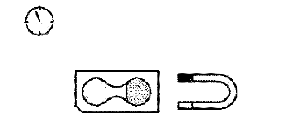
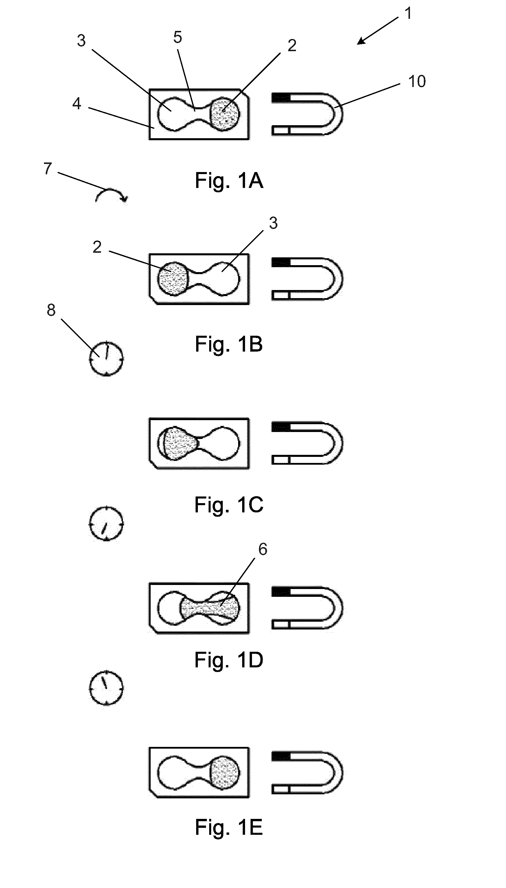
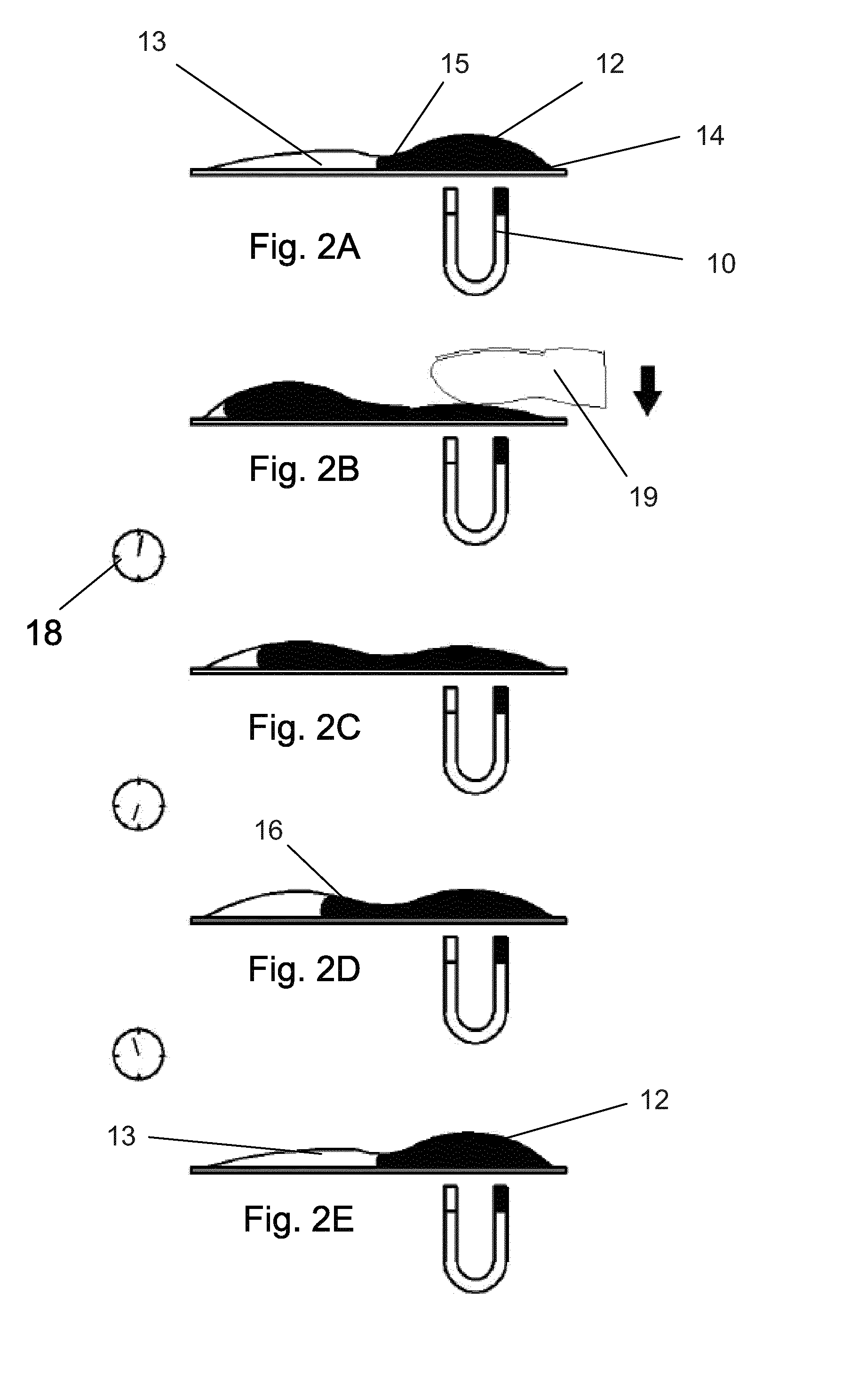
[0011]In a first aspect the present invention relates to a time delay indicator comprising two different compartments connected by a narrow channel or orifice e.g. like an hourglass.
[0012]One of the two compartments holds a flowable magnetic liquid which can flow from one co...
PUM
 Abstract
Description
Claims
Application Information