Magnetic time delay indicator and an injection device incorporating such

a time delay indicator and magnetic technology, applied in the field of injection devices, can solve the problems of user not remembering, inability to solve the problem of typical injection devices, and user choosing not to take his medication, etc., and achieve the effect of solving the problem of inconvenient use, low cost, and inability to integrate electronics

Inactive Publication Date: 2015-09-29
NOVO NORDISK AS
View PDF12 Cites 0 Cited by
  • Summary
  • Abstract
  • Description
  • Claims
  • Application Information

AI Technical Summary

Benefits of technology

[0011]Having regard to the above identified prior art, it is an object of the present invention to provide a time delay indicator which provides a visual indication output for signalling to a user that a predetermined time interval has lapsed, the timer being of less complex construction compared to prior art solutions. A further object is to provide a simple and cost-effective time delay indicator suitable for inclusion as an integral part of a disposable injection device and which enables easier operation of the injection device. Yet, a further object is to provide a time delay indicator which does not depend on mechanical means, but rather operates purely on magnetism.

Problems solved by technology

However, typical injection devices do not address the problem of a user not remembering when the last injection was administered.
Thus, there exist the potential hazard that the user chooses not to take his medication, or that he takes it twice.
However, for simpler injection devices such as disposable injection devices i.e. injection devices which are prefilled with a predetermined amount of liquid drug and discarded after use, the solution with integrated electronics will in most cases not be economically viable.
In addition, such a solution may not be environmentally acceptable due to the potential increase in the disposal of electronic components such as batteries etc.
However, in this magnetic time delay mechanism, the flowable magnetic material is shifted due to the gravity, thus requiring the two chambers to be physically located above and below each other.

Method used


Image

  • Magnetic time delay indicator and an injection device incorporating such
  • Magnetic time delay indicator and an injection device incorporating such
  • Magnetic time delay indicator and an injection device incorporating such

Examples


Embodiment Construction

[0011]Having regard to the above identified prior art, it is an object of the present invention to provide a time delay indicator which provides a visual indication output for signalling to a user that a predetermined time interval has lapsed, the timer being of less complex construction compared to prior art solutions. A further object is to provide a simple and cost-effective time delay indicator suitable for inclusion as an integral part of a disposable injection device and which enables easier operation of the injection device. Yet, a further object is to provide a time delay indicator which does not depend on mechanical means, but rather operates purely on magnetism.

[0012]The invention is defined in claim 1.

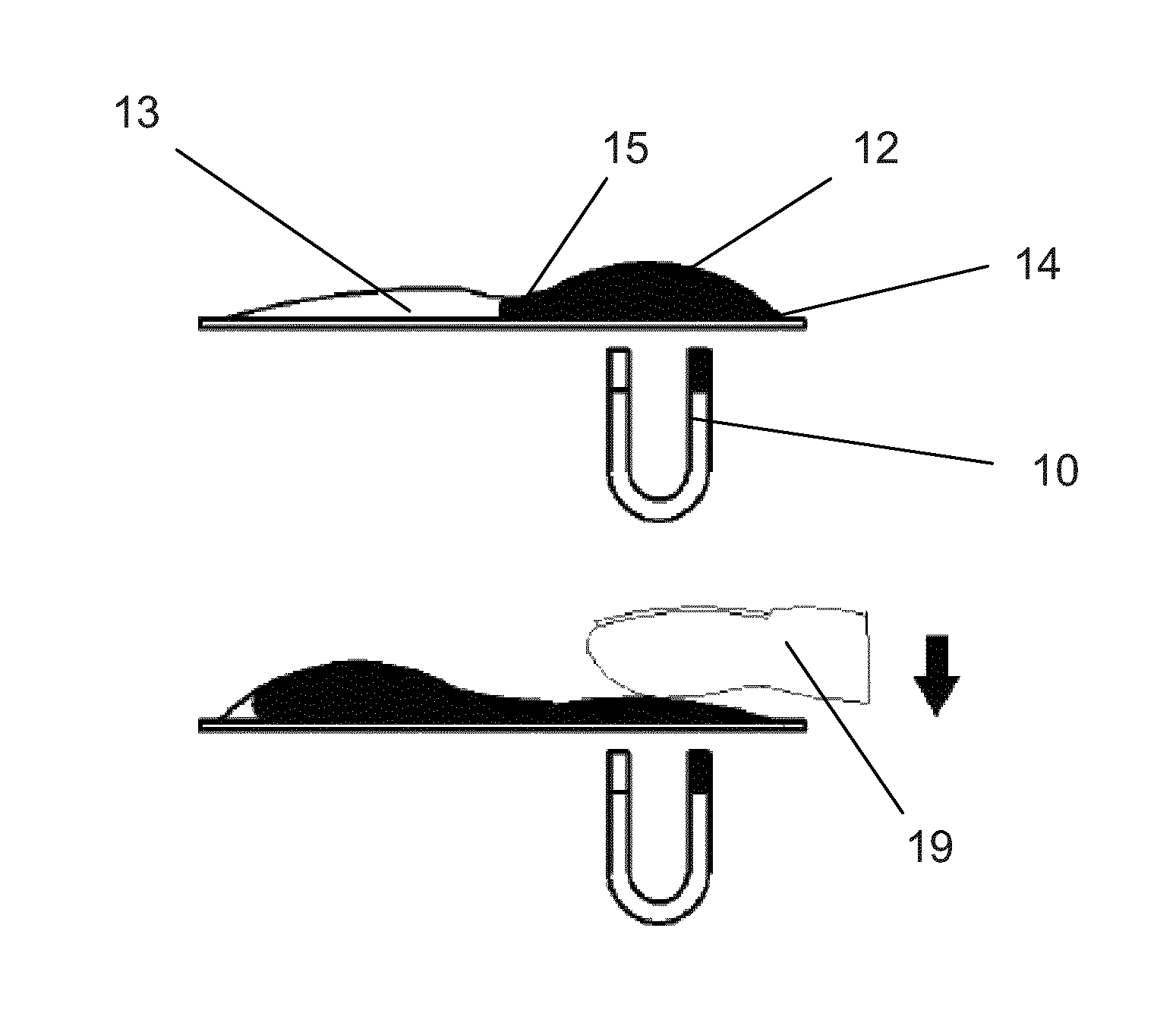
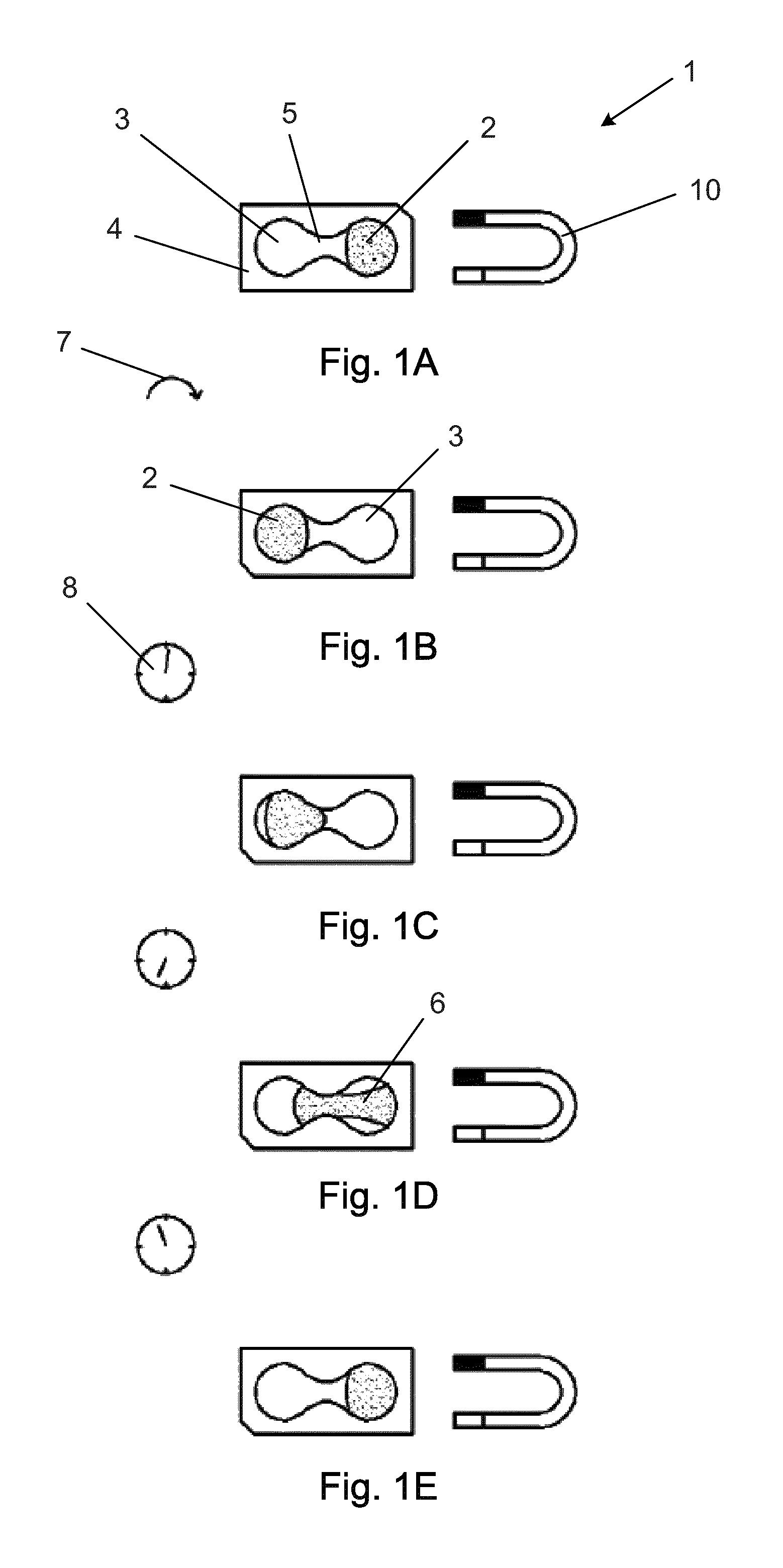
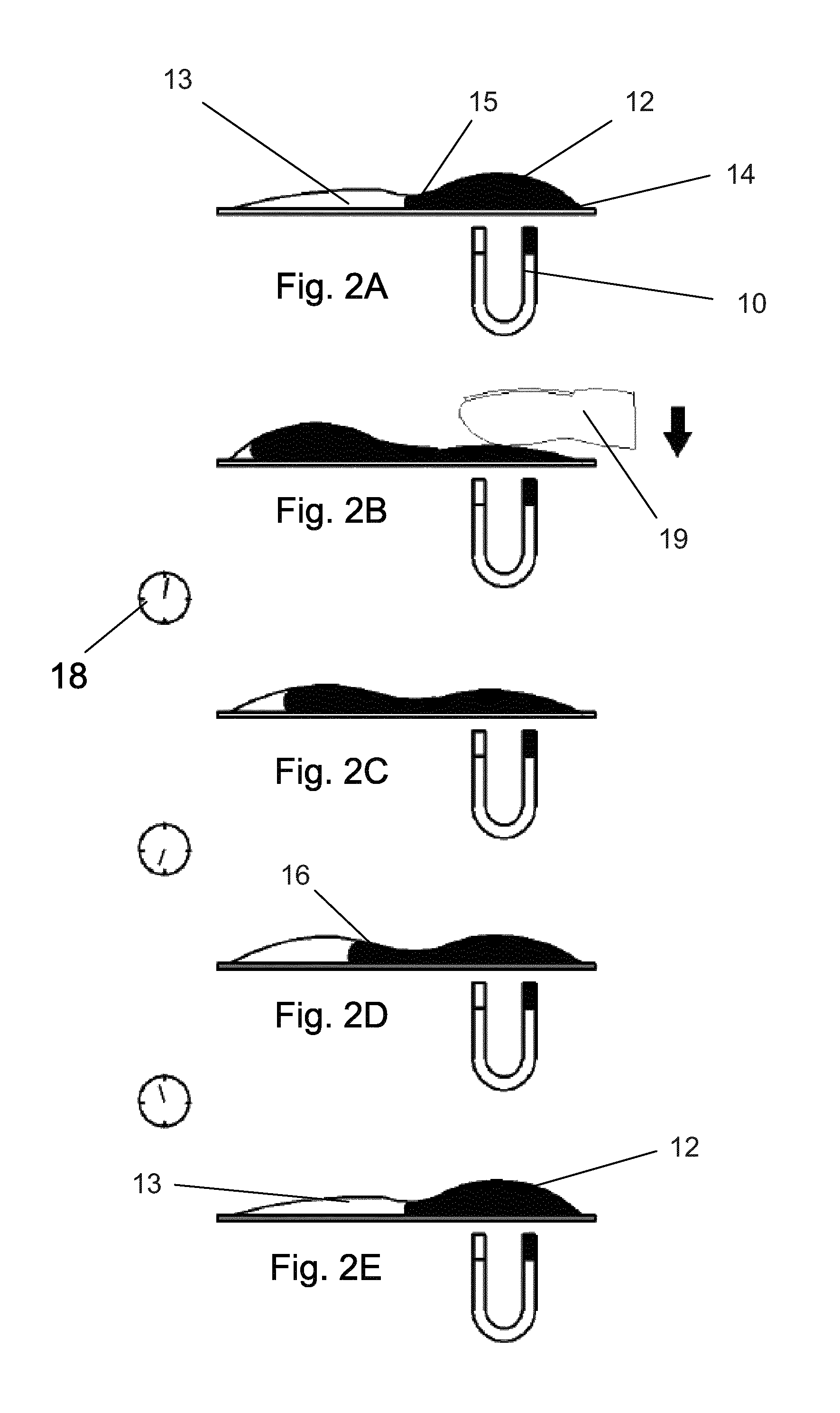
[0013]In a first aspect the present invention relates to a time delay indicator comprising two different compartments connected by a narrow channel or orifice e.g. like an hourglass.

[0014]One of the two compartments holds a flowable magnetic liquid which can flow from one co...


PUM


Abstract

The present invention relates to a time delay indicator (1) for an injection device for administering a drug into the body of a subject user wherein the time delay indicator is configured for indicating after administration that a dose of the drug actually has been administered and for maintaining this indication until lapse of a pre-determined time interval. The time delay indicator is based on a magnetic liquid (6) being physically moved by a magnet (10).

Description

CROSS-REFERENCE TO RELATED APPLICATIONS[0001]This application is a 35 U.S.C. §371 National Stage application of International Application PCT / EP2012 / 072719 (published as WO 2013 / 072412), filed Nov. 15, 2012, which claimed priority of European Patent Application 11189131.3, filed Nov. 15, 2011; this application claims priority under 35 U.S.C. §119 of U.S. Provisional Application 61 / 562,084; filed Nov. 21, 2011.THE TECHNICAL FIELD OF THE INVENTION[0002]The present invention relates to a time delay indicator for use with medical injection devices for administering a drug into the body of a user wherein the indicator is configured for visually indicating after administration of a dose of drug that a predetermined time interval has lapsed. Further, the present invention relates to an injection device incorporating such time delay indicator.DESCRIPTION OF RELATED ART[0003]People suffering from diabetes have to inject themselves with insulin at a daily basis. For this purpose a great numbe...

Claims


Application Information

Patent Timeline
Patent Type & Authority Patents(United States)
IPC IPC(8): G04F1/06A61M5/20A61J7/04G04F13/06H01H36/00A61M5/178
CPCA61M5/20A61J7/0409G04F1/066G04F13/06H01H36/00G04F1/06A61J1/1418A61J7/0418A61J7/0427A61J7/0436A61J7/0472A61M5/178A61M2005/2026A61M2205/507A61M2205/583
Inventor KIILERICH, EBBE
Owner NOVO NORDISK AS
Why Eureka
Try Eureka