
Mobile communication terminal and method

a mobile communication terminal and user interface technology, applied in the field of user interfaces of mobile communication terminals, can solve the problems of low degree of reversibility, unsuitable method for use in modern mobile communication terminals capable of displaying complex documents, and much more difficult task of determining the user agent, so as to improve the predictability of the shift of focus

Inactive Publication Date: 2006-11-23
NOKIA CORP
View PDF51 Cites 16 Cited by
  • Summary
  • Abstract
  • Description
  • Claims
  • Application Information

AI Technical Summary

Benefits of technology

[0021] This provides a method with improved predictability of the shift of focus from a first user interface element to a second user interface element in a complex user interface environment.
[0045] A third aspect of the present invention is a computer program product, directly loadable into a memory of a digital computer, comprising software code portions for performing a method according to the first aspect. This provides a computer program product, when executed, providing improved predictability of the shift of focus from a first user interface element to a second user interface element in a complex user interface environment.

Problems solved by technology

However, if the device only has a four-way or five-way navigation key or a joystick, the user agent has the much more difficult task of determining the user interface element that will receive focus solely based on:
However, the presented method is unsuitable for use in modern mobile communication terminals capable of displaying complex documents with focusable user interface elements, as the method provides a low degree of reversibility.
Consequently, there is a problem on how to manage navigation in documents displayed in a mobile communication terminal having only a limited input device.

Method used


Image

  • Mobile communication terminal and method
  • Mobile communication terminal and method
  • Mobile communication terminal and method

Examples


Embodiment Construction

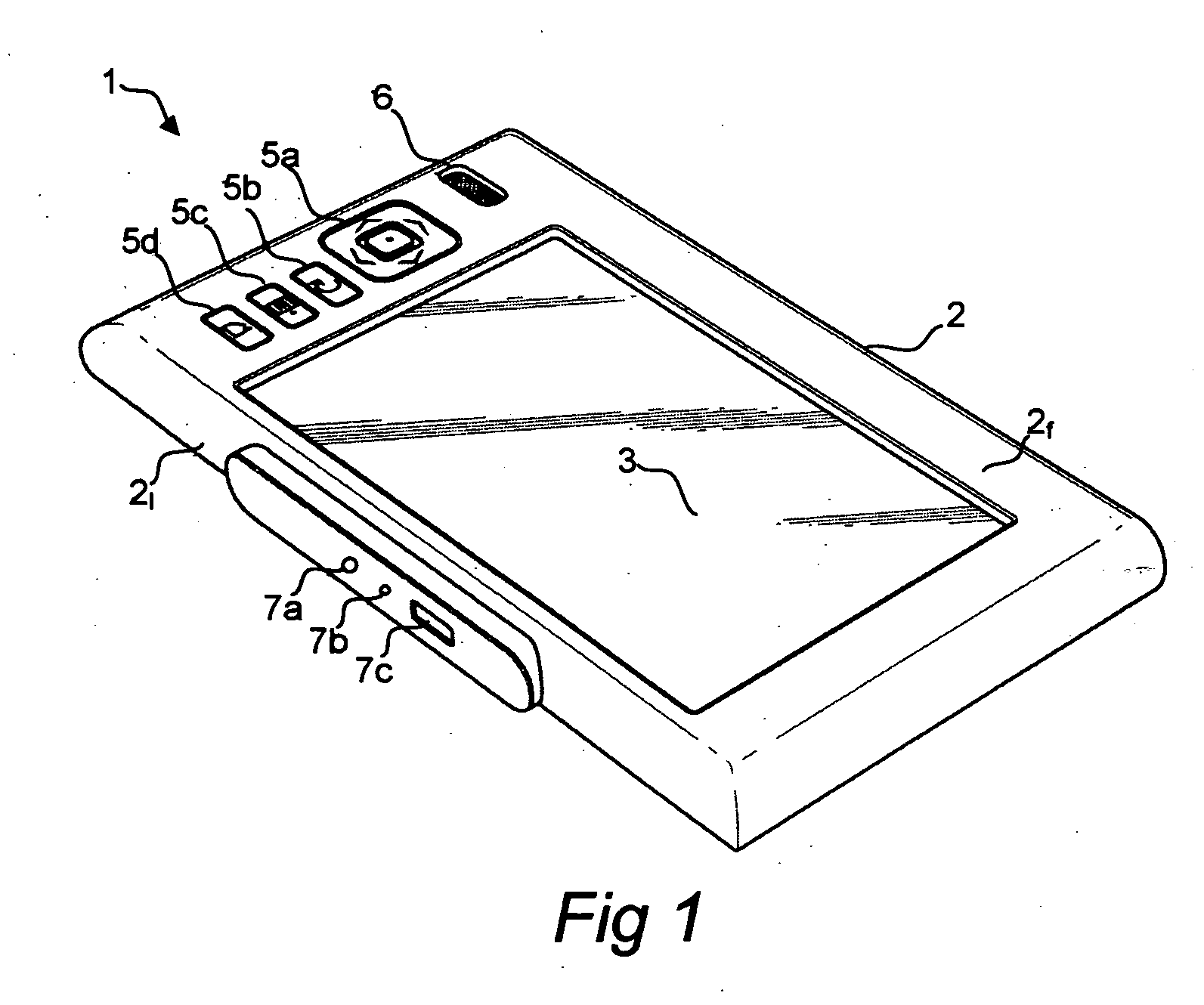
[0059]FIG. 1 is a perspective view of a mobile communication terminal in the form of a pocket computer according to one embodiment of the present invention.

[0060] The pocket computer 1 of the illustrated embodiment comprises an apparatus housing 2 and a display 3 provided at the surface of a front side 2f of the apparatus housing 2. Next to the display 3 a plurality of hardware keys 5a-d are provided, as well as a speaker 6.

[0061] More particularly, key 5a is a five-way navigation key, i.e. a key which is depressible at four different peripheral positions to command navigation in respective orthogonal directions (“up”, “down”, “left”, “right”) among information shown on the display 3, as well as depressible at a center position to command selection among information shown on the display 3. Key 5b is a cancel key, key 5c is a menu or options key, and key 5d is a home key.

[0062] At the surface of a short side 21 of the apparatus housing 2, there is provided an earphone audio termin...


PUM


Abstract

It is shown a method to move focus from a first user interface element to a second user interface element shown on a display of a mobile communication terminal, said mobile communication terminal further comprising an input device. The method comprises the steps of: detecting a directional input via said input device, said input indicating a desired direction to move; determining a set of candidate user interface elements being eligible to receive focus; for each candidate user interface element in said set of candidate user interface elements, determining a weighted distance between said candidate user interface element and said first user interface element by applying a function including, as an input parameter, an overlap between said first user interface element and said candidate user interface element in a direction orthogonal to said desired direction; and determining said second user interface element to be a particular candidate user interface element in said set of candidate user interface elements that has a minimum weighted distance to said first user interface element.

Description

CROSS-REFERENCE TO RELATED APPLICATIONS [0001] This application is a continuation-in-part of U.S. patent application Ser. No. 11 / 135,624 filed on May 23, 2005.FIELD OF THE INVENTION [0002] The present invention generally relates to user interfaces of mobile communication terminals, and more particularly to changing focus of user interface elements shown on displays of mobile communication terminals. BACKGROUND OF THE INVENTION [0003] Mobile communication terminals have changed dramatically in the last decade. With the first 2G terminals, the only real purpose was to make normal phone calls. Now with 2.5G (GPRS), CDMA2000 and UMTS technology, mobile communication terminals not only facilitate voice communication, but also digital communication such as text and multimedia messaging, as well as browsing content provided by Internet servers. [0004] The browser applications, also known as user agents, that are responsible for rendering documents, such as HTML, SVG, SMIL, containing focus...

Claims


Application Information

Patent Timeline
IPC IPC(8): G09G5/00G06F3/048G06F3/0481G06F3/0482G06F3/0485G06F3/0488
CPCG06F17/30905G06F3/0485G06F16/9577G06F9/00
Inventor KOIVISTO, ANTTI J.POPESCU, ANDREILIU, WEIGRASSEL, GUIDOROTO, VIRPIPAJUNEN, LASSEVAISANEN, MATTI
Owner NOKIA CORP
Learn More