Cylindrical lithium secondary battery

US20060263673A1Active Publication Date: 2006-11-23SAMSUNG SDI CO LTD

Image

  • Cylindrical lithium secondary battery
  • Cylindrical lithium secondary battery
  • Cylindrical lithium secondary battery

Examples


Embodiment Construction

[0037] Reference will now be made in detail to the present embodiments of the present invention, examples of which are illustrated in the accompanying drawings, wherein like reference numerals refer to the like elements throughout. The embodiments are described below in order to explain the present invention by referring to the figures.

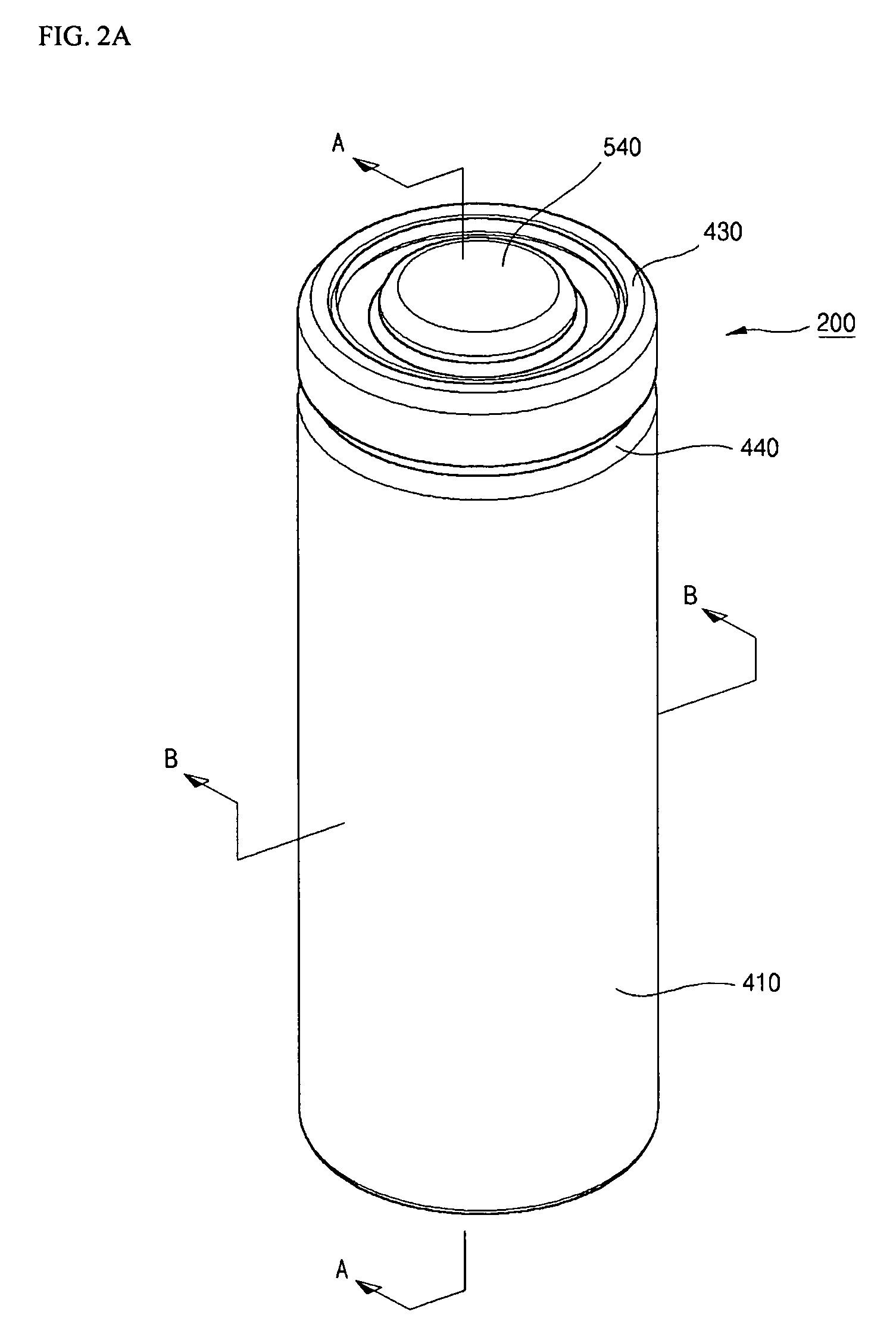
[0038]FIG. 2A is a perspective view of a cylindrical lithium secondary battery according to an embodiment of the present invention. FIG. 2B is a cross-sectional view along the A-A line of FIG. 2A. FIG. 2C is a cross-sectional view along the B-B line of FIG. 2A.

[0039] Referring to FIGS. 2A to 2C, a cylindrical lithium ion secondary battery 200 includes an electrode assembly 300 which generates a voltage difference at charging / discharging time, a cylindrical case 400 which contains the electrode assembly 300, a cap assembly 500 which is assembled at an upper portion of the cylindrical case 400 and prevents the electrode assembly 300 from separation, a...


PUM


Abstract

A cylindrical lithium secondary battery includes an electrode assembly which has a first electrode plate, a second electrode plate, and a separator provided between the first electrode plate and the second electrode plate, is wound in a spiral shape, and has a central space at the center of winding; a core member which is inserted into the central space of the electrode assembly; a case having a space for containing the electrode assembly; and a cap assembly which is connected to an upper portion of the case so as to seal the case. The core member is formed in a tube shape having a gap along a longitudinal direction, which divides the core member into a body portion and left and right lateral end portions, wherein an imaginary arc line extending from an outer circumferential surface of the body portion of the core member defines an imaginary circumference, and wherein the left and right lateral end portions are located inside the imaginary circumference and comprise a pair of first bending portions, inwardly bending and symmetrically disposed with respect to the gap, and a pair of second bending portions bending in a rotation direction that is opposite to the inwardly bending rotational directions of the first bending portions.

Description

CROSS-REFERENCE TO RELATED APPLICATION [0001] This application claims the benefit of Korean Patent Application No. 2005-35301, filed on Apr. 27, 2005, in the Korean Intellectual Property Office, and of Korean Patent Application No. 2005-41422, filed on May 18, 2005 in the Korean Intellectual Property Office, the disclosures of which are incorporated herein in their entirety by reference. BACKGROUND OF THE INVENTION [0002] 1. Field of the Invention [0003] Aspects of the present invention relate to a cylindrical lithium ion secondary battery, and more particularly, to a cylindrical lithium ion secondary battery having an improved stability with respect to external pressure. [0004] 2. Description of the Related Art [0005] In general, a cylindrical lithium ion secondary battery includes an electrode assembly that is wound substantially in the form of a cylinder, a cylindrical can that is connected to the electrode assembly, an electrolytic solution that is infused inside the can to allo...

Claims


Application Information

Patent Timeline
23 Nov 2006
Publication
US20060263673A1
IPC
H01M4/00; H01M10/052; H01M10/05; H01M10/0525; H01M10/0587
CPC
H01M2/022; H01M2/345; Y02E60/122; H01M10/0525; H01M10/0587; H01M10/0431; Y02E60/10; H01M50/107
Inventors
KIM, JONG KU; WOO, SOON KI