Method and system for minimizing leakage of a distending medium during endoscopic procedures

a technology of endoscopic procedures and distending mediums, applied in the field of methods and systems for minimizing leakage of distending mediums during endoscopic procedures, can solve the problems of undesirable leakage, no endoscopic procedure can be performed, and endoscopic surgery is difficult or impossible, so as to reduce or minimize the leakage of liquids

Active Publication Date: 2006-11-23
KUMAR BV
View PDF36 Cites 1 Cited by
  • Summary
  • Abstract
  • Description
  • Claims
  • Application Information

AI Technical Summary

Benefits of technology

[0018] The present invention overcomes disadvantages of the prior art, such as those noted above, by providing a system for reducing or minimizing the leakage of a liquid or gaseous distending medium on at least one side of an endoscopic instrument. The present invention also provides a method for allowing two endoscopic instruments having different outer diameters to be interchanged without the risk of liquid or gaseous leak. A method of preventing an endoscopic instrument from accidentally slipping out of a tissue cavity, or from accidentally traversing beyond any desired depth inside a tissue cavity, is also provided.

Problems solved by technology

Such ballooning of the tissue cavity is called “cavity distension.” No endoscopic procedure can be performed if an adequate distension of the tissue cavity is not achieved and maintained.
If leakage occurs, the tissue cavity collapses and adequate mechanical separation of the cavity walls cannot be achieved and the mechanical separation cannot be maintained, thus making endoscopic surgery difficult or impossible.
However, in the static distension system, the outflow port and the outflow channel are missing or not used in the endoscope, and either gas or fluid can be instilled via the inflow channel of the endoscope.
Such leakage is undesirable and, thus, the terms “cavity leak” and “cavity leakage” (which are used interchangeably) refer to leakage of a distending liquid or gas by the sides of an endoscope, including endoscopic surgical instruments that could enter into the tissue cavity through a cannula or which may be introduced directly (that is without a cannula).
Especially at higher intra articular pressures, the distending fluid may leak around the sides of the shaver or around the sides of other endoscopic instruments inserted into the joint cavity.
Such leakage is undesirable as it leads to a reduction in the intra articular pressure, which necessitates a greater inflow rate in order to maintain the same intra articular pressure.
In addition, if a peristaltic pump is used, for example, on the inflow side, such increased flow rate could culminate in an increased frequency and amplitude of the cavity pressure pulsations caused by the peristaltic pump, which will ultimately lead to an increased turbulence inside the joint cavity.
The cavity leak could also lead to a fluid leakage on the floor, it could also cause extracapsular extravasation of fluid, and it could also impede a surgeon from correctly calculating the total volume of fluid extravasation, as there is no reliable method of measuring the total volume of fluid which spills on the floor.
The cavity leakage could also occur if two endoscopes having different outer diameters were interchanged.
Such a leak can also occur if the initial slit given over the fascia, to facilitate the insertion of the trocar cannula, is relatively larger than required.
Such cavity leakage could make hysteroscopic surgery difficult as well as dangerous.
However, it is impractical and difficult to use such sheaths and the result, in terms of minimizing or avoiding cavity leakage, is also unpredictable.
Further, if endoscopes must be interchanged during the course of an endoscopic procedure, it is inconvenient, from a practical standpoint, to remove and then install a sheath having a different outer diameter.
The incorporation of the sheaths also restricts the maneuverability of the endoscope, thereby requiring greater force to move the endoscope in a to and fro, or rotary, motion.

Method used


Image

  • Method and system for minimizing leakage of a distending medium during endoscopic procedures
  • Method and system for minimizing leakage of a distending medium during endoscopic procedures
  • Method and system for minimizing leakage of a distending medium during endoscopic procedures

Examples


Embodiment Construction

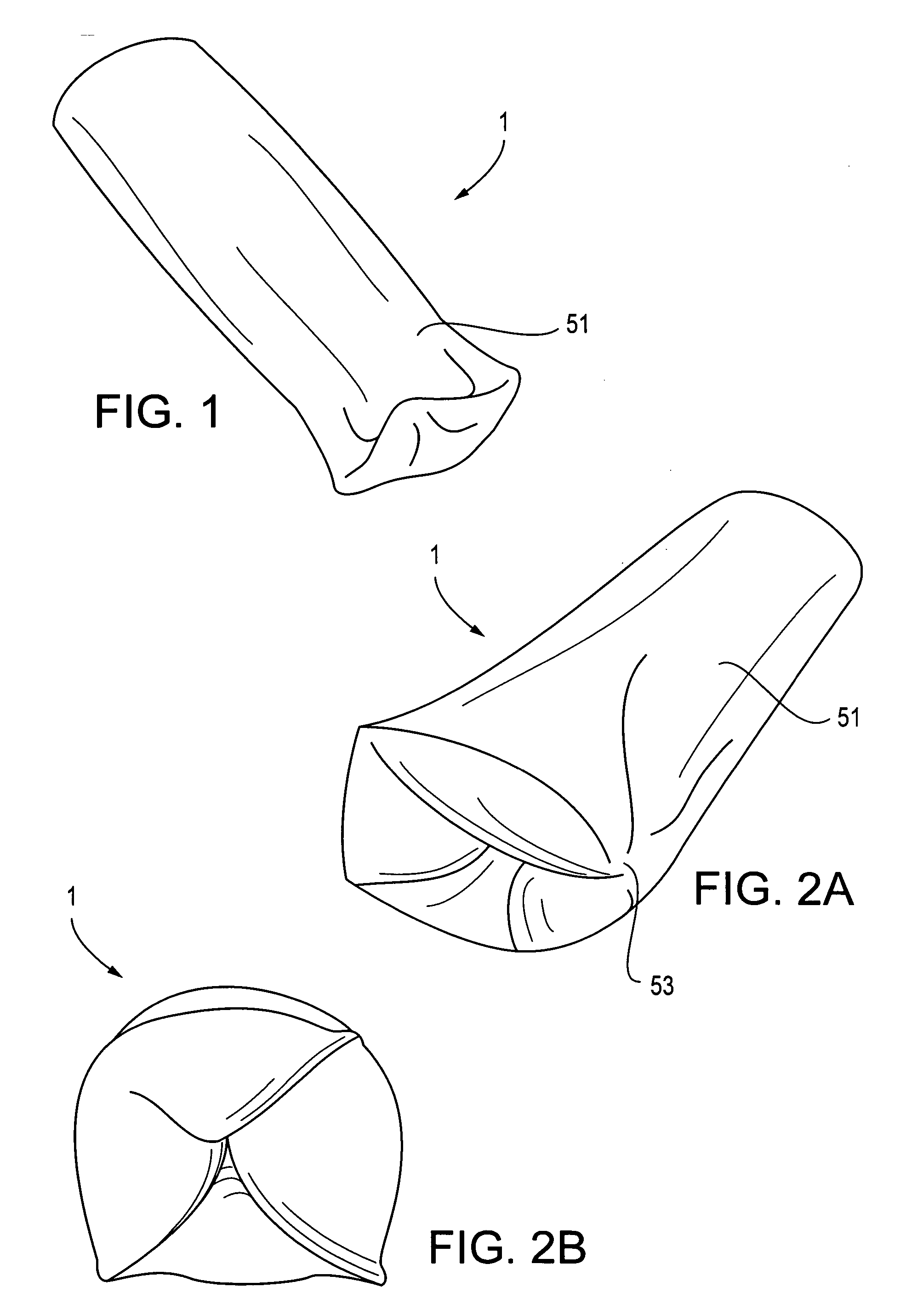
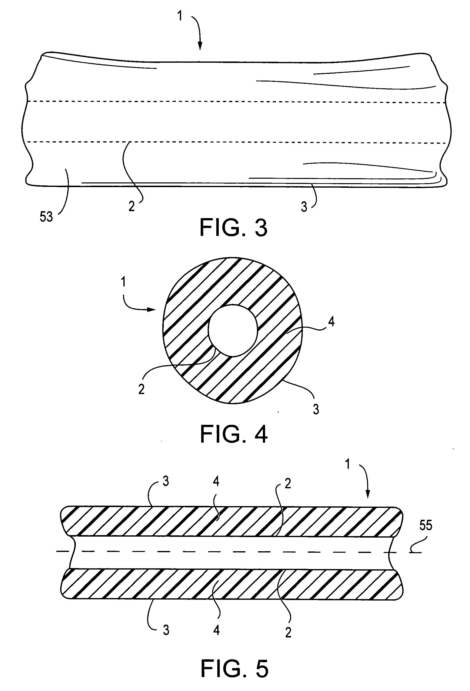
[0039] The term “flexible tubular sheath” as used in the present invention is intended to encompass any double-wall hollow body which is open at both ends and which is filled with a fluid, either a liquid or gas, or a combination of a liquid and gas. The term “flexible tubular sheath” also refers to a flexible containment structure whose walls are made of a strong, relatively thick elastic distensible material, such that the cavity could be filled with only a maximum predetermined volume of liquid or gas beyond which the cavity pressure would rise steeply and the structure would burst. As used in the present invention, the term “flexible tubular sheath” is not limited to a tube, or to a tube having a cylindrical or oval cross-section, but rather the term “flexible tubular sheath” is intended to encompass a structure that has an inner hollow body defined by double walls and filled with a liquid or gas, or a combination of liquid or gas.

[0040] The terms “tissue cavity opening” and “c...


PUM


Abstract

A system for minimizing leakage of fluid distending media by the sides of the endoscopic instrument in endoscopic procedures such as arthroscopy, hysteroscopy or laparoscopy. A double-wall flexible tubular sheath having walls containing pressurized fluid is mounted over an endoscopic instrument. The double-wall flexible tubular sheath moves in and out of a natural opening of a tissue cavity or through an incision made in the cavity wall.

Description

FIELD OF THE INVENTION [0001] The present invention relates to a system which avoids or minimizes leakage of a distending liquid or gaseous medium by the sides of an endoscopic instrument during endoscopic procedures, such as arthroscopic, hysteroscopic or laparoscopic surgery. BACKGROUND OF THE INVENTION [0002] Endoscopic surgery is becoming increasingly popular because it is a minimally invasive form of surgery, it is associated with less pain, and the patients can return back to normal work relatively early with minimal loss of working days. [0003] In endoscopic surgeries, an endoscope is typically introduced into a body cavity via the natural opening of the cavity or, alternatively, a minute hole is made in the wall of the cavity through which the endoscope is introduced to visualize the interior of the body tissue cavity and to perform endoscopic surgical procedures. For the purposes of the present invention, the term “tissue cavity opening” shall be used to refer to a natural ...

Claims


Application Information

Patent Timeline
Patent Type & Authority Applications(United States)
IPC IPC(8): A61B1/00
CPCA61B17/3421A61B17/3431A61B17/3423
Inventor KUMAR, ATULKUMAR, ALKA
Owner KUMAR BV
Why Eureka
Try Eureka