
Three-dimensional volumetric display apparatus and method

a volumetric display and three-dimensional technology, applied in the direction of static indicating devices, simultaneous indication of multiple variables, instruments, etc., can solve the problems of damage to natural work style incongruity of stereoscopic display, etc., to achieve the effect of efficient representation of the surface texture of an obj

Inactive Publication Date: 2006-11-30
FUJIFILM BUSINESS INNOVATION CORP
View PDF11 Cites 47 Cited by
  • Summary
  • Abstract
  • Description
  • Claims
  • Application Information

AI Technical Summary

Benefits of technology

[0014] Accordingly, the present invention provides a three-dimensional volumetric display device which can efficiently represent a surface texture of an object on a volumetric shape model.

Problems solved by technology

In this method, since special glasses such as the polarization glasses must be used, there is a problem that a natural work style may be damaged.
Furthermore, since only a stereo image viewed from any view point is displayed and parallax is not varied although a position of the eye is changed, there is a problem that stereoscopic display is observed with incongruity.
However, since parallax is not varied, there is a problem that stereoscopic display is observed with incongruity, similar to the polarization glasses.
Since a distance between a point which can be stereoscopically viewed (eye position) and an optimal position is very narrow, for example, about ±10 mm, the eye must be always fixed to any position, and thus eyestrain or physical fatigue is apt to occur.
In addition, simultaneous stereoscopic viewing is limited to each individual person and information on data can not be shared with participants.
As such, the polarization glasses or the lenticular method is not suitable as the stereoscopic display method for the collaboration which is performed by many people.
In this method, since the projected image is the cross-sectional image, it is not possible to represent a surface texture.
In this method, it is not possible to efficiently represent a surface texture of an object.
Even in this method, it is not possible to efficiently represent a surface texture of an object.

Method used


Image

  • Three-dimensional volumetric display apparatus and method
  • Three-dimensional volumetric display apparatus and method
  • Three-dimensional volumetric display apparatus and method

Examples


Embodiment Construction

[0032] Hereinafter, an embodiment of the present invention will be described with reference to the attached drawings.

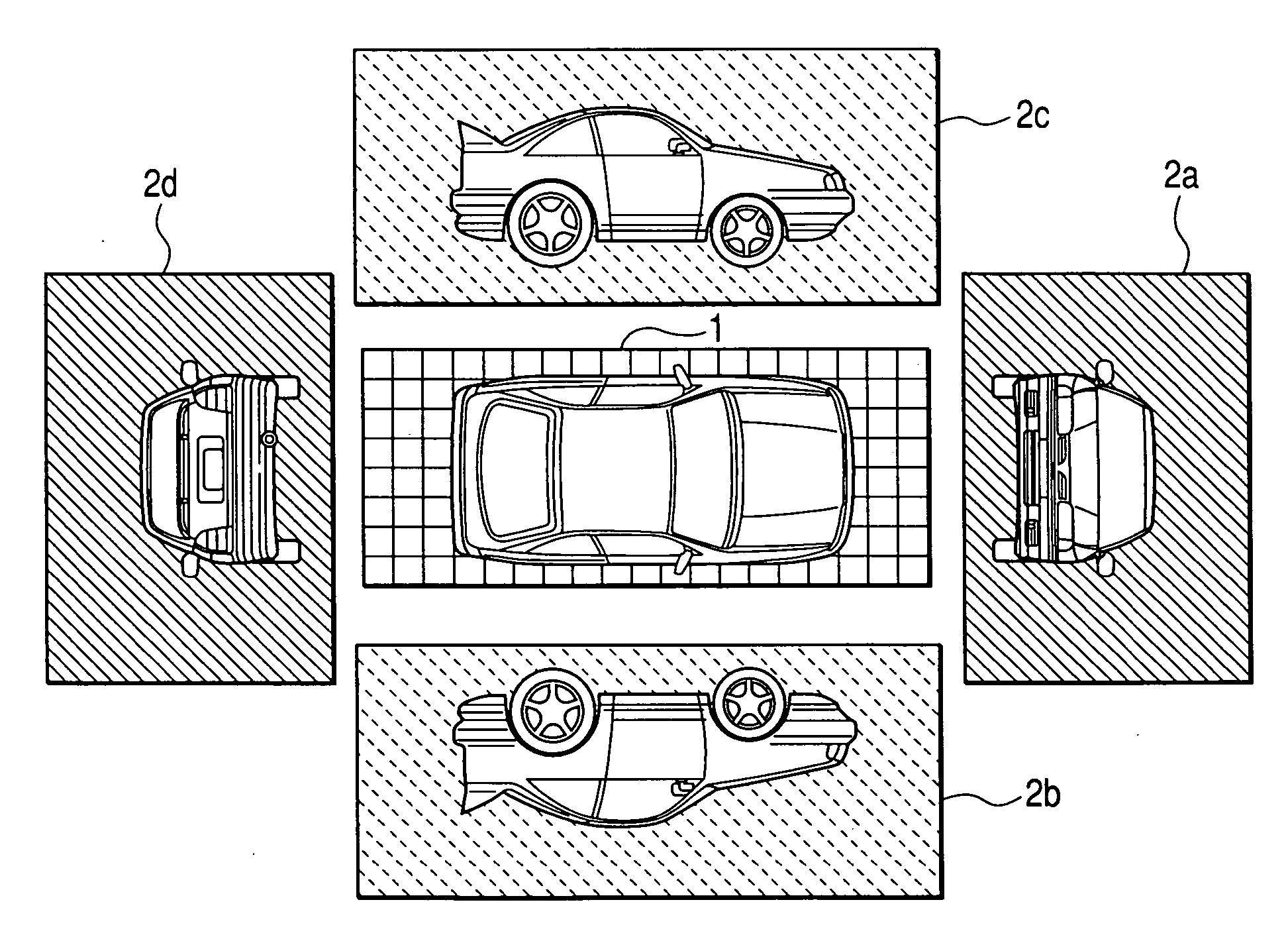
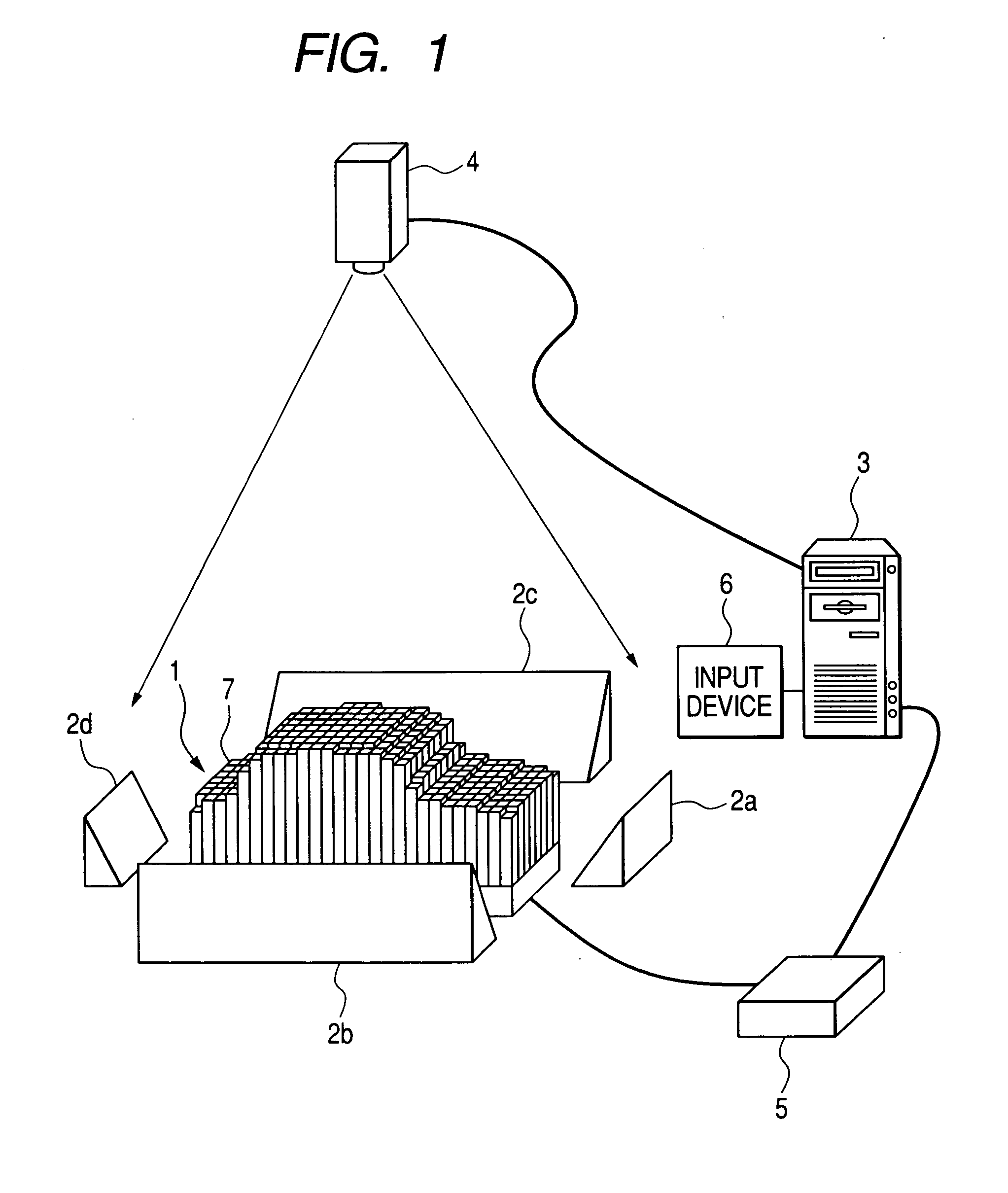
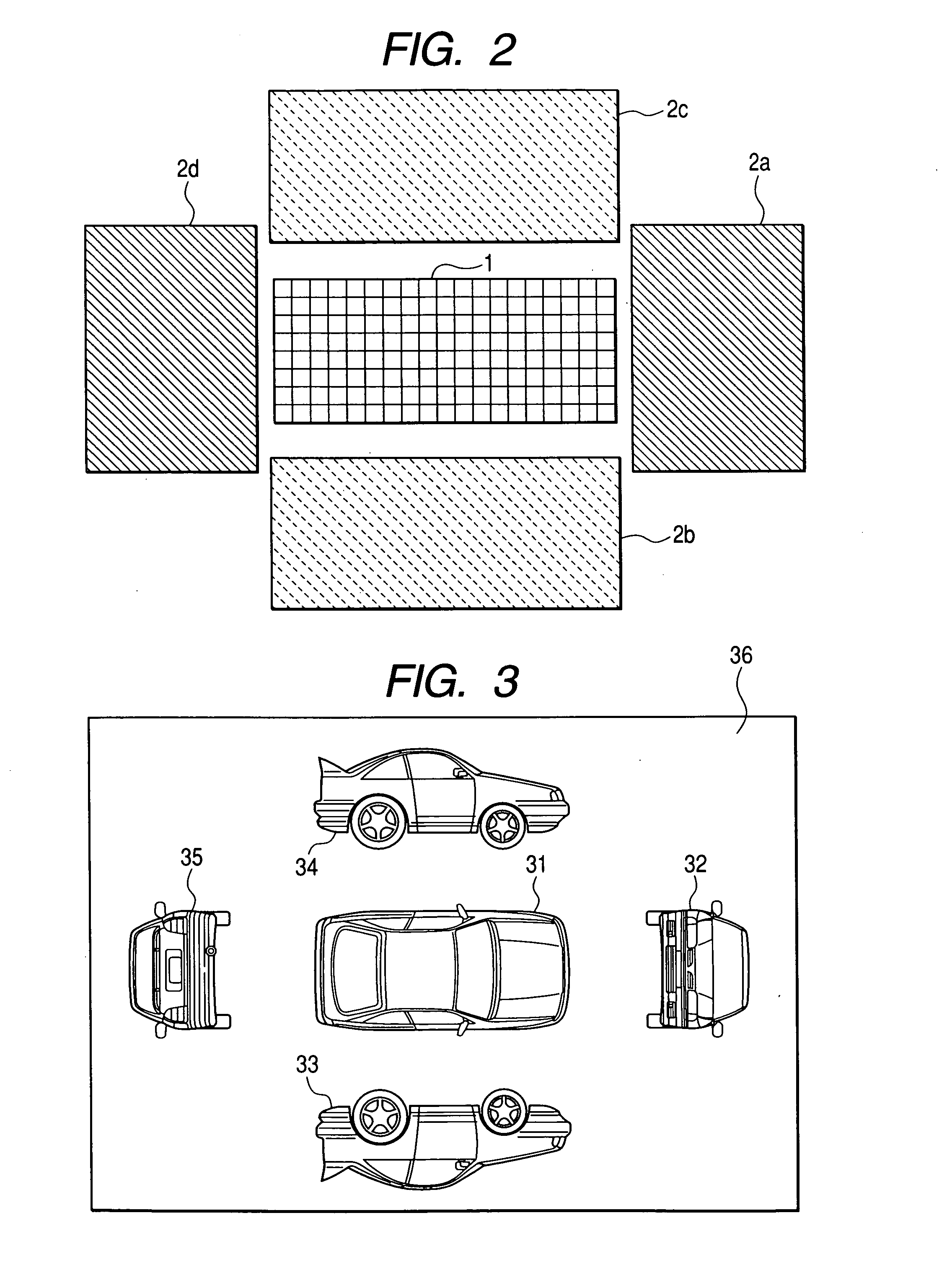
[0033]FIG. 1 illustrates a configuration of a volumetric display device according to an embodiment of the present invention. As shown, the present embodiment includes a volumetric shape model 1, reflection mirrors 2a to 2d disposed at the side surfaces of the volumetric shape model 1, a control device 3 for storing image information of surface textures of the upper surface and the side surfaces of the volumetric shape model, and a projector 4 which directly projects a surface texture image of the upper surface of the volumetric shape model 1 onto the volumetric shape model 1 and projects surface texture images of the side surfaces of the volumetric shape model 1 onto the volumetric shape model 1 through the reflection mirrors 2a to 2d, based on the image information from the control device 3. The control device 3 may be composed of a computer such as a personal compu...


PUM


Abstract

A volumetric display apparatus, includes: a volumetric shape model having a side surface and an upper surface; a reflection mirror disposed at the side surface; a control device which stores image information of surface textures of the upper surface and the side surface; and a projector that projects an image of the surface texture of the upper surface onto the upper surface and which projects an image of the surface texture of the side surface onto the side surface via the reflection mirror, based on the image information from the control device.

Description

BACKGROUND OF THE INVENTION [0001] 1. Field of the Invention [0002] The present invention relates to a three-dimensional volumetric display apparatus, and more particularly, to a three-dimensional volumetric display apparatus which projects a surface texture image of a volumetric shape model onto the volumetric shape model to perform three-dimensional volumetric display. [0003] 2. Background Art [0004] When plural people discuss any one subject, a conference has been actively held due to collaboration which can obtain a better result by sharing information, intention, or idea with one another. At this time, for the purpose of exhibiting data in a visible and understandable form, an opportunity of using a three-dimensional volumetric display (three-dimensional volumetric display device) has increased. [0005] A stereoscopic display technology has been suggested in various forms. As a representative example, there are the following polarizing glasses or a lenticular method. [0006] The ...

Claims


Application Information

Patent Timeline
IPC IPC(8): G01D7/02G03B21/00G03B21/28G03B35/18G06T15/04H04N13/04
CPCH04N13/0488H04N13/388G06T17/00
Inventor NISHIKAWA, OSAMUMIYAZAKI, JUN
Owner FUJIFILM BUSINESS INNOVATION CORP
Learn More