Method and apparatus for rendering shadows

a shadow and shadow technology, applied in the field of computer graphics, can solve the problems of insufficient support for fine detail rendering of typical shadow rendering techniques, such as fur or hair, and inability to accurately represent shadows from semi-transparent surfaces and or semi-transparent surfaces or volumes, such as fog or smoke, and achieve the effect of improving data access and improving memory performan

Inactive Publication Date: 2006-06-08
PIXAR ANIMATION
View PDF0 Cites 31 Cited by
  • Summary
  • Abstract
  • Description
  • Claims
  • Application Information

AI Technical Summary

Benefits of technology

[0030] A method and apparatus for rendering shadows are described. Embodiments of the invention implement a two-dimensional array or map of depth-based functions, such as a visibility function in z. During rendering of an object scene, these functions are accessed via lookup operations to efficiently determine the function value for a sample point at a given depth. The use of visibility functions allows for partial light attenuation effects such as partially blocking surfaces, semi-transparent surfaces and volumetric elements, to be accurately modeled over a range of z values. Thus, in contrast to prior art shadow map methods in which a point on a surface is either fully lit or completely shadowed with respect to a light source, it is possible for a point on a surface to be more realistically rendered as being fractionally lit by a light source.
[0032] In one or more embodiments, the visibility function is piecewise linear, implemented as a sequence of vertices, each comprising a depth (z) value and corresponding function value. Compression is achieved by minimizing the number of vertices needed to represent the visibility function within a desired error tolerance. Multiple visibility functions (such as individual color visibility functions for R, G and B) may be efficiently represented by a sequence of vertices, each comprising one depth value and two or more function values respectively associated with the individual visibility functions at the given depth value. A flag may be associated with each map location to specify whether that location is monochrome (one visibility function) or color (separate RGB visibility functions).
[0033] During rendering, a visibility value is obtained from the stored map by performing a lookup in x and y to determine the specific function in the map, performing a linear or binary search of the corresponding sequence of vertices to locate the linear segment containing the desired depth or z value, and interpolating the function value along that linear segment. Efficient lookups are facilitated by storing a pointer to the most recently accessed segment, and initiating a subsequent search from that segment.
[0035] To improve data access during the rendering process, portions of a map may be cached. The cache contains multiple cache lines that are each capable of storing a tile of map data. A map tile may comprise, for example, a two-dimensional subset of map locations. Because different visibility functions may contain varying numbers of vertices, the storage allocation size of map tiles may also vary. For more efficient memory performance, the sizes of cache lines may be dynamically resized as map tiles are swapped, to reflect the individual storage requirements of the current map tiles resident in the cache.

Problems solved by technology

Unfortunately, typical shadow rendering techniques do not satisfactorily support rendering of finely detailed elements, such as fur or hair.
Also, because surfaces are generally classified as either “lit” or “unlit,” shadows from semitransparent surfaces and volumes, such as fog, cannot be accurately represented.
While shadow maps may be satisfactory for rendering shadows of large, opaque objects, shadow maps do not work well for finely detailed geometry, such as hair, or semitransparent surfaces or volumes, such as fog or smoke.
This means that, in the case of very fine geometry, stratified sampling does no better than unstratified sampling.
Since such conditions are rarely satisfied in practice, shadow maps for high-quality hair rendering are typically large and slow.
However, standard shadow maps do not behave well under compression.
Compression in x and y would entail fewer samples and thus greater error.
Compression in z, such as by reducing the number of bits representing z values in the shadow map, introduces a roundoff error in specifying the location of a first blocking surface.
Where the roundoff error causes ZMAP to be less than the actual value, the top surface will appear to be behind ZMAP, resulting in erroneous “self-shadowing” of the top surface.
In either of these scenarios, visible rendering errors will result.
However, lossless compression is acceptable, but the compression ratios are relatively small and provide no significant space benefit.
Thus, compression is not a viable solution for standard shadow maps.
Ray casting can generate accurate shadows, but on scenes with very complex geometry, ray casting is too expensive in terms of time and memory.
It is also difficult, other than by using an expensive area light source, to soften shadows for artistic purposes, which in the case of standard shadow maps is achieved by simply increasing the filter width.
The main drawback is that 3D textures have a relatively coarse resolution, as well as a limited range and low accuracy in z (which creates bias problems).
A 3D texture with sufficient detail to capture accurate surface shadows would be prohibitively large.
Multi-layer depth images have been applied to the problem of shadow penumbras, but this technique otherwise has the same limitations as ordinary shadow maps.

Method used


Image

  • Method and apparatus for rendering shadows
  • Method and apparatus for rendering shadows
  • Method and apparatus for rendering shadows

Examples


Embodiment Construction

[0064] The invention is a method and apparatus for rendering shadows. In the following description, numerous specific details are set forth to provide a more thorough description of embodiments of the invention. It will be apparent, however, to one skilled in the art, that the invention may be practiced without these specific details. In other instances, well known features have not been described in detail so as not to obscure the invention.

[0065] In this specification, “map location” is used interchangeably with “pixel” to mean an element of any shape or form in the image that is in consideration.

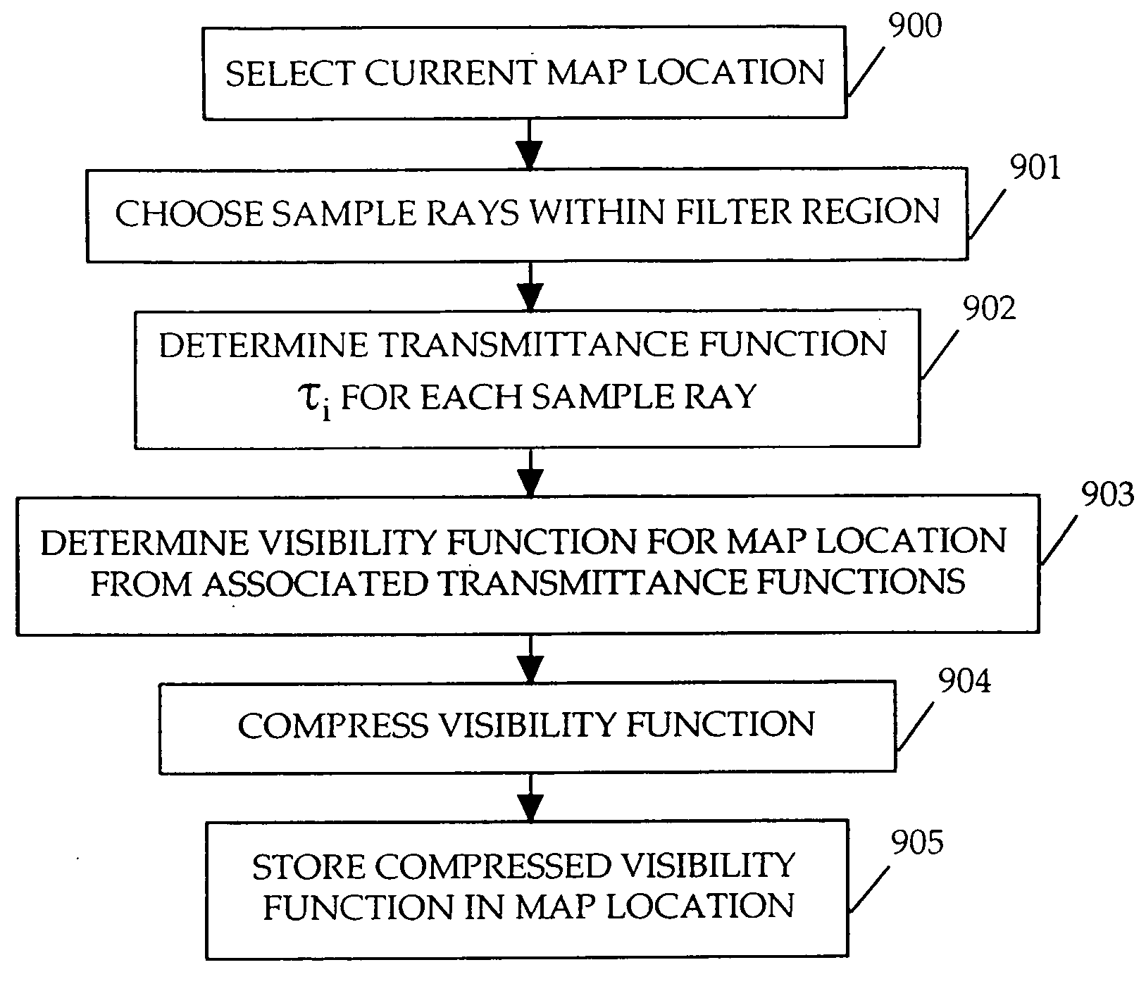
Deep Shadow Map Overview

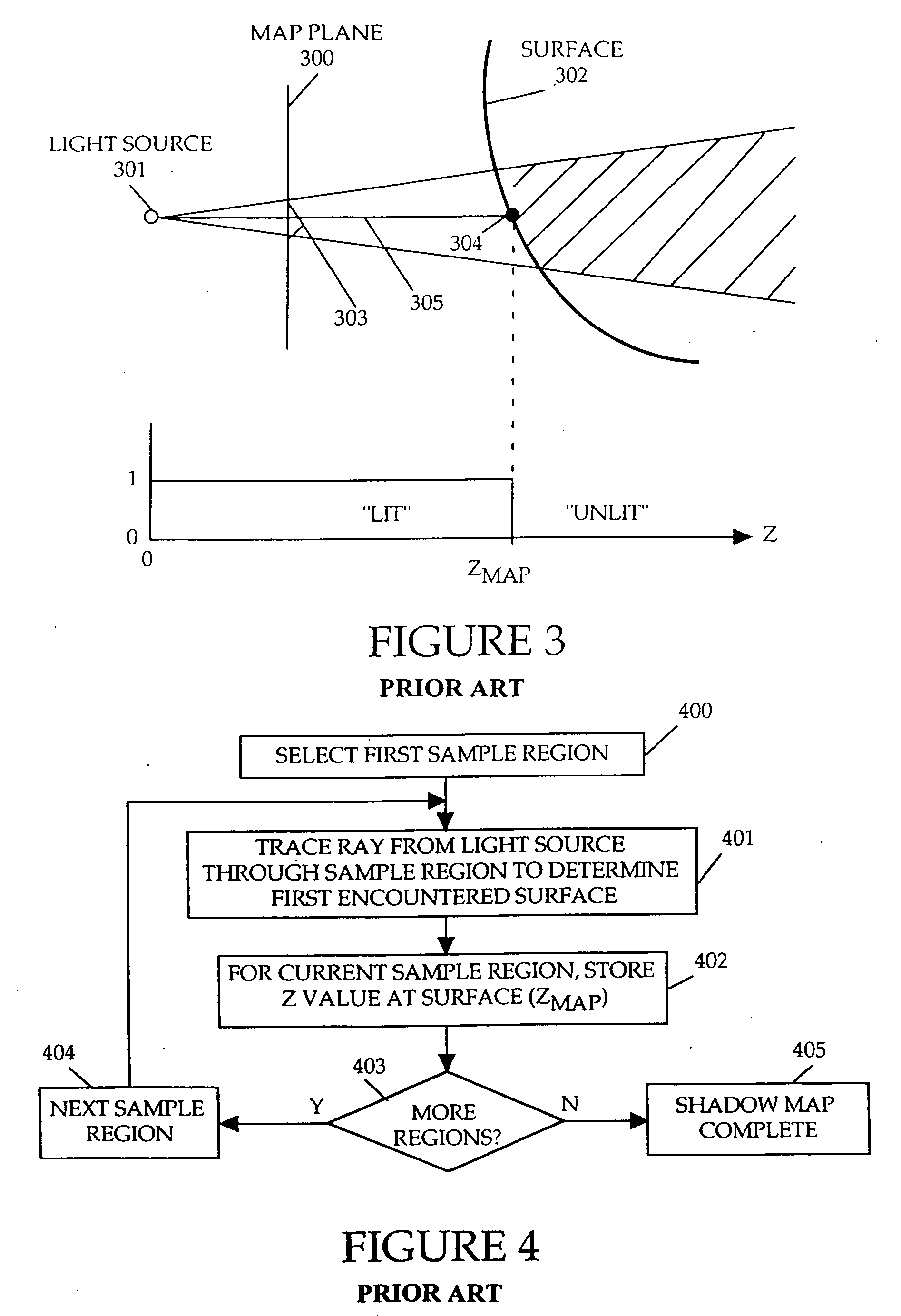
[0066] Embodiments of the invention employ a new form of shadow map, referred to herein as a “deep shadow map,” to provide greater flexibility and realism in the rendering of shadows. As opposed to shadow maps of the prior art that treat shadows in a binary manner (i.e., a surface is either lit or unlit) based on a single stored depth value, deep shadow maps pe...


PUM


Abstract

A method and apparatus for rendering shadows. A pre-rendering process implements a two dimensional array or map of depth-based functions, such as a visibility function in z. During rendering of an object scene, these functions are accessed via lookup operations to efficiently determine the function value for a sample point at a given depth. The use of visibility functions allows for partial light attenuation effects. Each visibility function is computed by filtering multiple transmittance functions obtained by casting sample rays from a light source onto an object scene. The visibility function is implemented as a sequence of vertices. Colored shadows are modeled by vertices comprising a depth value and separate visibility function values for red, green, and blue light at a given depth value. Compression is achieved by minimizing the number of vertices needed to represent a visibility function within a desired error tolerance.

Description

BACKGROUND OF THE INVENTION [0001] 1. Field of the Invention [0002] This invention relates to the field of computer graphics, and, more specifically, to graphical rendering of shadows. [0003] 2. Background Art [0004] In computer graphics, images are often created from three-dimensional objects modeled within a computer. The process of transforming the three-dimensional object data within the computer into viewable images is referred to as rendering. Single still images may be rendered, or sequences of images may be rendered for an animated presentation. One aspect of rendering involves the determination of lighting effects on the surface of an object, and in particular, the accurate representation of shadows within the rendered image. Unfortunately, typical shadow rendering techniques do not satisfactorily support rendering of finely detailed elements, such as fur or hair. Also, because surfaces are generally classified as either “lit” or “unlit,” shadows from semitransparent surfac...

Claims


Application Information

Patent Timeline
Patent Type & Authority Applications(United States)
IPC IPC(8): G06T15/50G06T15/60G06T15/40
CPCG06T15/06G06T15/40G06T15/60
Inventor LOKOVIC, THOMAS DAVIDVEACH, ERIC HUGH
Owner PIXAR ANIMATION
Why Eureka
Try Eureka