Location detection method, location detection system and location detection program

a technology of location detection and location detection, applied in the field of method of measuring the location of the receiver, can solve the problems of increasing the power consumption of the terminal, increasing the period of time to obtain the results of measurement, etc., and achieve the effect of preventing the increase in the time and the consumption power required

Inactive Publication Date: 2005-03-08
HITACHI LTD
View PDF13 Cites 74 Cited by
  • Summary
  • Abstract
  • Description
  • Claims
  • Application Information

AI Technical Summary

Benefits of technology

According to the present invention, the correct location of the terminal can be measured by preventing the increase in the time and the consumption power required for the positioning. Moreover, a location information supplying device and a location information supplying system according to the present invention is useful to recognize positioning errors to determine continuation or termination of the positioning operation.

Problems solved by technology

However, the increase in the number of samples for the averaging operation and the elongation of the integration time for the signal detection reduces measurement or positioning errors, but increases a period of time to obtain results of measurement.
This increases power consumption of the terminal.

Method used


Image

  • Location detection method, location detection system and location detection program
  • Location detection method, location detection system and location detection program
  • Location detection method, location detection system and location detection program

Examples


first embodiment

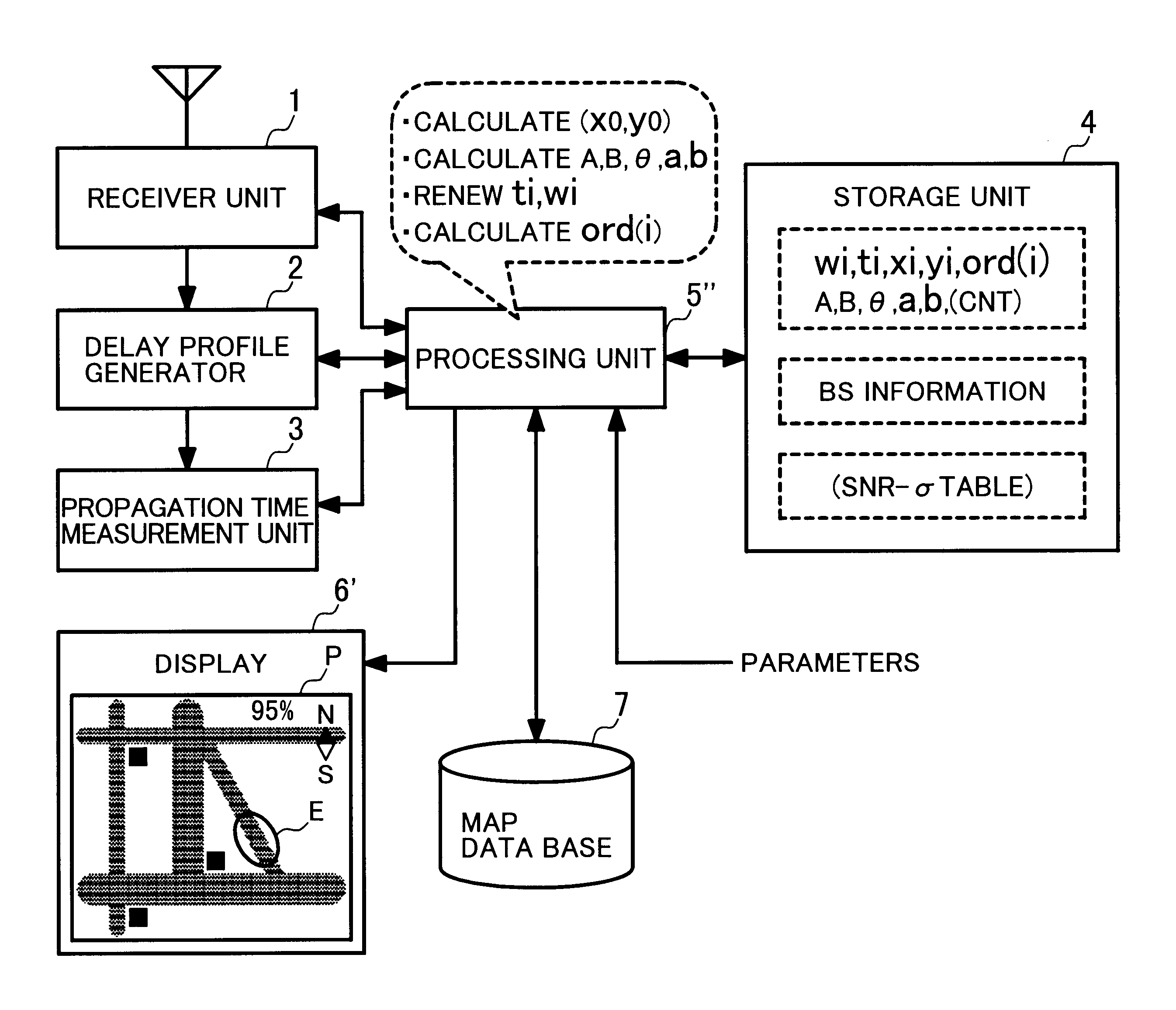
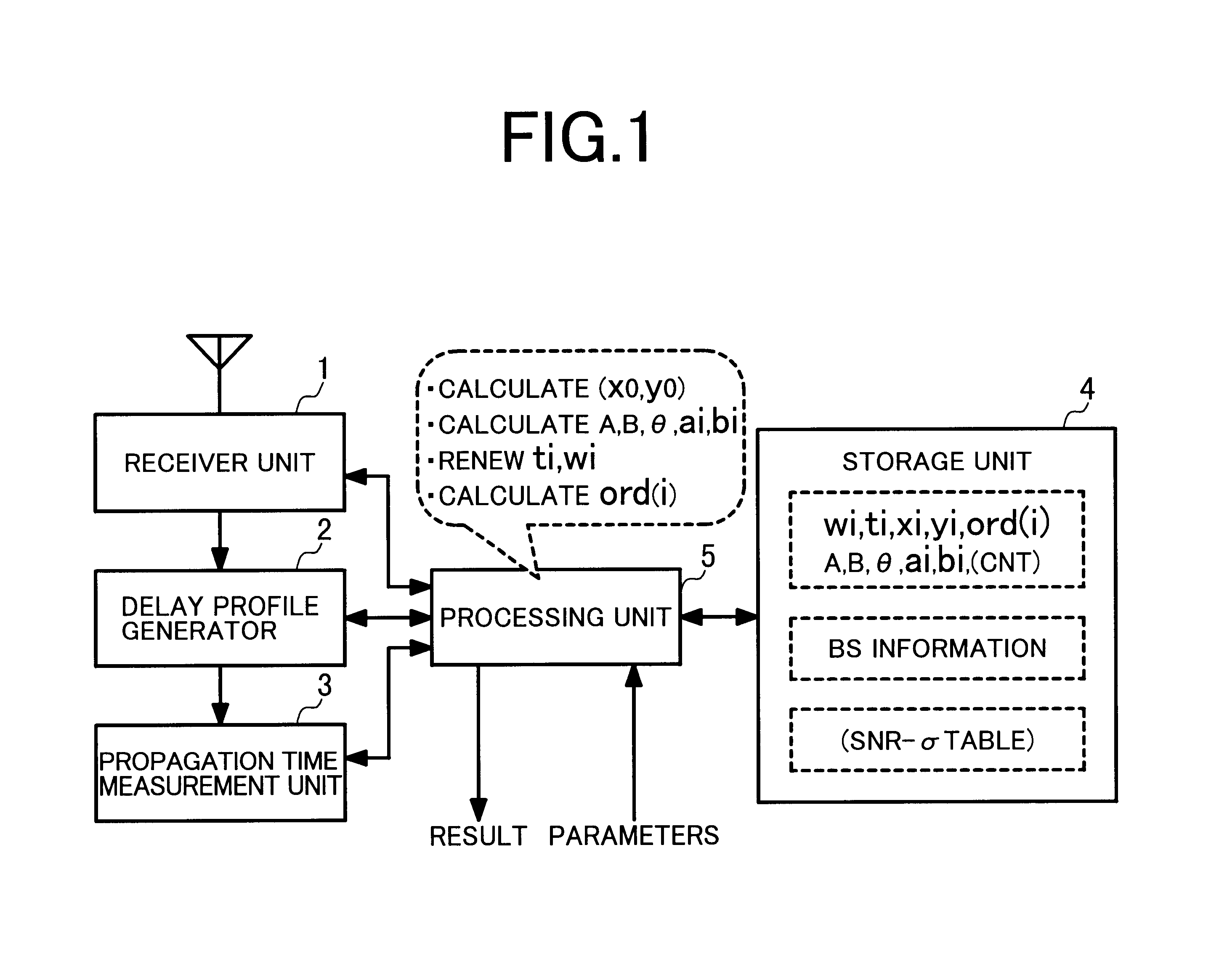
FIG. 1 shows in a block diagram a primary configuration of a positioning unit in the present invention.

In this system, a receiver unit 1 receives a signal from a base station, not shown, under control of a processing unit 5, conducts a baseband filtering operation for the signal, and outputs a signal resultant from the filtering operation to a delay profile generator 2. The receiver unit 1 also measures power of noise and outputs an obtained noise power to the processing unit 5.

According to the signal from the receiver unit 1, the delay profile generator 2 generates a delay profile for a base station indicated by the processing unit 5 and outputs the delay profile to a signal delay time measurement unit 3 and the processing unit 5.

The signal delay time measurement unit 3 analyzes the delay profile from the delay profile generator 2 under control of the processing unit 5 to determine propagation delay time of the signal from the base station and outputs the propagation delay time to ...


PUM


Abstract

A positioning method, which is related to a technique to measure a correct position of a terminal by preventing time required for the position measurement, of calculating a position of a receiver according to signals from a plurality of wireless transmitters includes a first step of measuring propagation delay time of the signal from each of the wireless transmitters and calculating a position of the receiver and a standard deviation about measuring distance error, a second step of calculating a positioning error of the receiver a third step of determining, according to the positioning error calculated by the second step, wireless transmitters in directions nearer to a direction in which the positioning error is large, and a fourth step of re-detecting signals from the wireless transmitters determined by the third step and thereby re-calculating the position of the receiver.

Description

BACKGROUND OF THE INVENTIONThe present invention relates to a method of measuring a location of a receiver according to propagation delay time of a signal transmitted from a wireless transmitter, and in particular, to a method of measuring a location of a receiver with high precision according to propagation delay time of a signal sent from a mobile base station.There has been proposed a technique to detect in a mobile communication system a location of a terminal device or a terminal according to a signal sent from a base station. For example, JP-A-7-181242 (laid-open on Jul. 21, 1995) proposes a technique in which in a Code Division Multiple Access (CDMA) system, a location of a terminal is measured by obtaining time differences between transmission times of a pseudo-noise (PN) code from respective base stations by use of locations of the base stations and propagation times of signals sent from the base stations to the terminal.SUMMARY OF THE INVENTIONErrors in the location measur...

Claims


Application Information

Patent Timeline
Patent Type & Authority Patents(United States)
IPC IPC(8): G01S1/00G01S1/02G01S5/14G01S19/25
CPCG01S5/14G01S1/022
Inventor OGINO, ATSUSHIKUWAHARA, MIKIOISHIFUJI, TOMOAKI
Owner HITACHI LTD
Why Eureka
Try Eureka