Acoustic logging while drilling tool having raised transducers

a technology of transducer and acoustic recording, which is applied in the direction of instruments, borehole/well accessories, surveys, etc., can solve the problems of complicated determination of shear wave slowness, affecting the accuracy of logging, so as to reduce the standoff distance, improve the signal strength of received guided waves, and reduce the effect of stando

Active Publication Date: 2011-11-24
SCHLUMBERGER TECH CORP
View PDF8 Cites 18 Cited by
  • Summary
  • Abstract
  • Description
  • Claims
  • Application Information

AI Technical Summary

Benefits of technology

[0014]Exemplary embodiments of the present invention provide several technical advantages. For example, deployment of the transmitter and / or the receivers on a blade reduces the standoff distance to the borehole wall. The reduced standoff tends to significantly improve the signal strength of received guided waves without an increase in transmitter power or receiver sensitivity. This in turn tends to significantly improve the accuracy of shear slowness measurements, particularly in acoustically slow formations.
[0015]Moreover, embodiments of the invention, having a reduced standoff distance, may advantageously enable leaky shear wave arrivals (also referred to in the art as evanescent shear wave arrivals) to be detected. Shear wave slownesses may then be directly determined in acoustically slow formations using the leaky shear wave arrivals, thereby potentially improving accuracy as compared to prior art techniques.
[0016]Furthermore, the use of blades, when properly configured, advantageously centralizes the tool in the borehole, which in turn tends to reduce the dependence of the received waveforms and measured slownesses on the tool azimuth in the borehole. This feature of the invention may be particularly useful in making logging while drilling acoustic anisotropy measurements.

Problems solved by technology

Additionally, as used in the art, there is not always a clear distinction between the terms LWD and MWD.
In acoustically slow formations, in which the velocity of shear waves is less than the speed of sound in the drilling fluid (mud), shear wave slowness determination is known to be complicated by poor transmission of shear wave energy across the boundary between the formation and the borehole.
In some boreholes this can be problematic, for example, if the borehole diameter is much larger than the tool body, and the tool is located near the center of the borehole.
Excitation of sufficiently strong guided waves can also be a problem if the borehole is deviated (and / or the tool is decentralized in a large borehole) and the transmitter and receiver face away from the closest borehole wall.
However, because acoustic energy may also be transmitted from the transmitter to the receivers through the tool body as tool noise, these modifications to the transmitter power and / or receiver sensitivity also increase tool noise.
But this tends to be a complex solution and adds to the expense of the tool.
Another problem commonly encountered in shear wave slowness determination is the aliasing of the compressional wave signal in acoustically slow formations.
This “aliasing effect” may mask or mimic the presence of a shear wave signal, and tends to be particularly harmful when the alias is close to an expected shear wave arrival time.
The effect of aliasing can be diminished by reducing the distance between acoustic receivers, but this also reduces array coverage which can increase uncertainty in coherence analysis, unless more receivers are added, at more expense.
Yet another difficulty encountered in shear wave slowness determination is that guided wave propagation tends to be highly dispersive in LWD applications.
Although STC analysis is widely used, dispersive effects in the received waveforms can reduce the reliability of the STC analysis.
In many applications, values for each of these other factors are not accurately known, which can in turn lead to errors in the shear slowness estimate.
Moreover, in some formations large dispersion correction may be required, which can further contribute to uncertainty in the shear wave slowness.
Another drawback with the aforementioned techniques is that logging while drilling tools configured for transmitting and / or receiving the relatively pure acoustic modes mentioned earlier require highly complex transmitter and / or receiver configurations, which tend to be expensive.
The difficulty in generating such acoustic signals is also known to be further exacerbated by tool eccentricity in the borehole (e.g., in highly deviated wells in which the tool typically lies on the low side of the borehole).
Moreover, the use of such complex transmitters and receivers in severe downhole conditions including extreme temperatures and pressures, severe mechanical shocks and vibrations (up to 650 G per millisecond) tends to reduce tool reliability.

Method used


Image

  • Acoustic logging while drilling tool having raised transducers
  • Acoustic logging while drilling tool having raised transducers
  • Acoustic logging while drilling tool having raised transducers

Examples


Embodiment Construction

[0027]With respect to FIGS. 1 through 6, it will be understood that features or aspects of the embodiments illustrated may be shown from various views. Where such features or aspects are common to particular views, they are labeled using the same reference numeral. Thus, a feature or aspect labeled with a particular reference numeral on one view in FIGS. 1 through 6 may be described herein with respect to that reference numeral shown on other views.

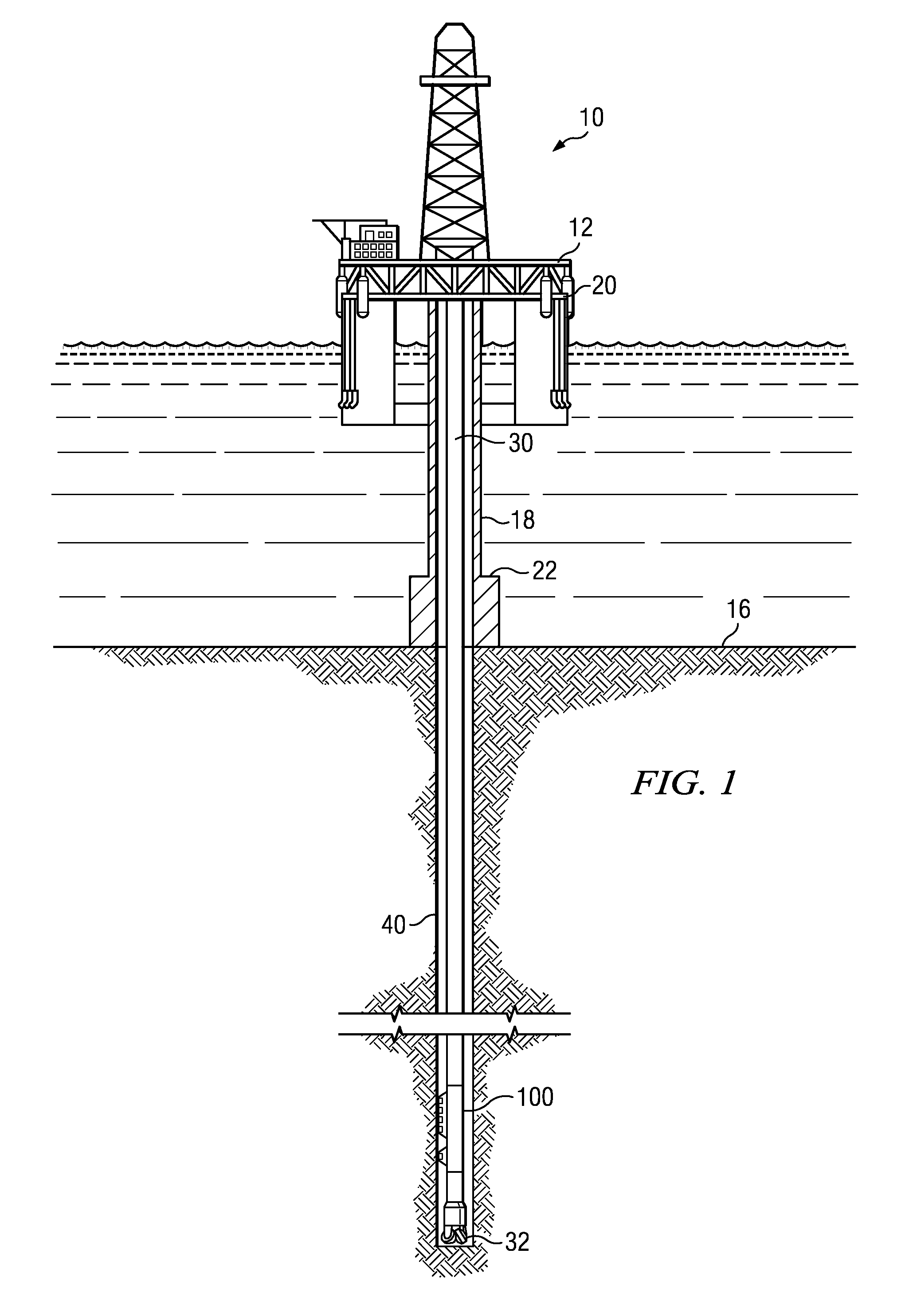
[0028]FIG. 1 depicts one exemplary embodiment of an acoustic logging while drilling (LWD) tool 100 according to this invention in use in an offshore oil or gas drilling assembly, generally denoted 10. In FIG. 1, a semisubmersible drilling platform 12 is positioned over an oil or gas formation (not shown) disposed below the sea floor 16. A subsea conduit 18 extends from deck 20 of platform 12 to a wellhead installation 22. The platform may include a derrick and a hoisting apparatus for raising and lowering the drill string 30, which, as sh...


PUM


Abstract

An acoustic logging while drilling tool includes an acoustic transmitter and a linear array of acoustic receivers. At least one of the transmitter and the linear array of receivers is deployed on a blade having an outer diameter greater than that of the tool body. In preferred embodiments the transmitter and linear array are each deployed on a distinct blade. Deployment of the transmitter and/or the receivers on a blade reduces the standoff distance to the borehole wall which tends to improve the signal strength of received guided waves without an increase in transmitter power or receiver sensitivity.

Description

RELATED APPLICATIONS[0001]None.FIELD OF THE INVENTION[0002]The present invention relates generally to acoustic logging of subterranean formations. More particularly, this invention relates to an acoustic logging while drilling tool in which at least one of a transmitter and a receiver is deployed on a blade.BACKGROUND OF THE INVENTION[0003]The use of acoustic (e.g., audible and / or ultrasonic) measurement systems in prior art downhole applications, such as logging while drilling (LWD), measurement while drilling (MWD), and wireline logging applications, is well known. Such acoustic measurement systems are utilized in a variety of downhole applications including, for example, borehole caliper measurements, measurement of drilling fluid properties, and the determination of various physical properties of a formation. In one application, acoustic waveforms may be generated at one or more transmitters deployed in the borehole. The acoustic responses may then be received at an array of lon...

Claims


Application Information

Patent Timeline
Patent Type & Authority Applications(United States)
IPC IPC(8): E21B47/16G01V1/40
CPCG01V1/46E21B17/1078
Inventor WANG, TSILI
Owner SCHLUMBERGER TECH CORP
Why Eureka
Try Eureka